
Frequency generator and method for generating frequency

a generator and frequency technology, applied in the field of low-power open-loop fractional frequency generators, can solve the problems of increasing the noise of output signals, increasing the power consumption of output signals, and increasing power consumption

Active Publication Date: 2020-06-09
SHENZHEN GOODIX TECH CO LTD
View PDF10 Cites 4 Cited by
  • Summary
  • Abstract
  • Description
  • Claims
  • Application Information

AI Technical Summary

Benefits of technology

The solution enables efficient fractional frequency division with reduced power consumption and noise, achieving the desired frequency signals while minimizing circuit area and operational complexity.

Problems solved by technology

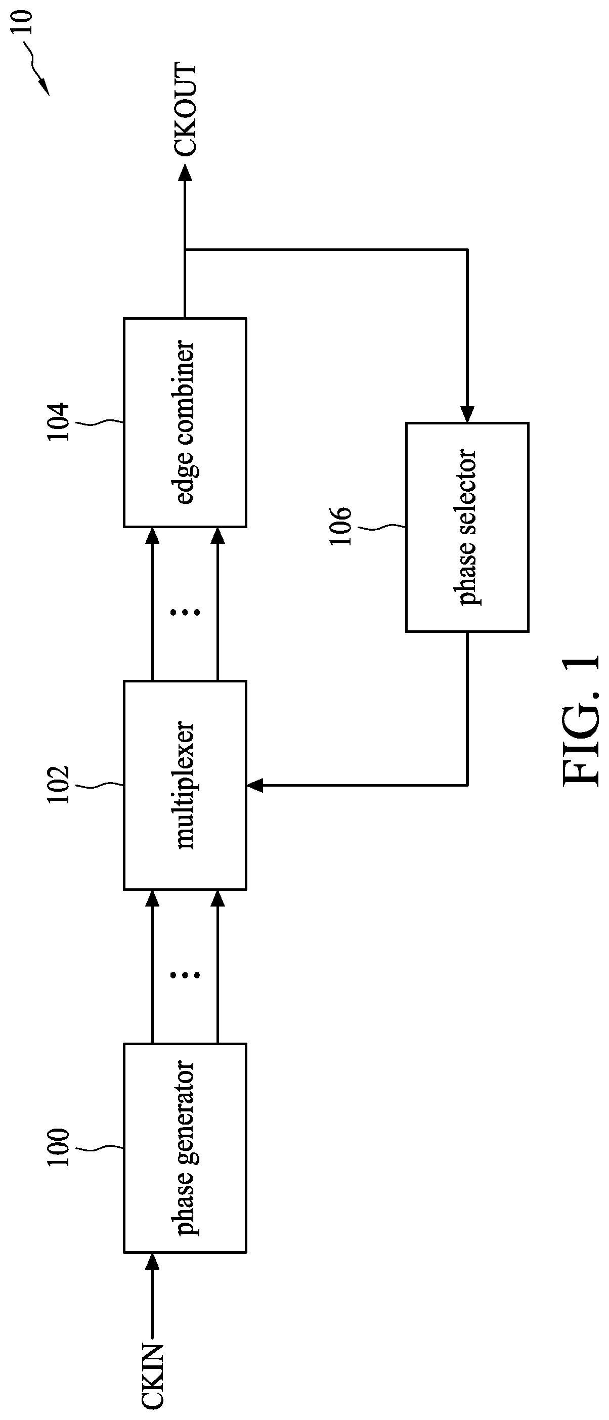
It should be noted that when performing the fractional frequency division operation, more phase generating units are required in the phase generator 100 in order to improve the resolution of the plurality of phase signals, thereby resulting in additional power consumption; moreover, the mismatch among phase generating units also results in the increased noise of the output signal.
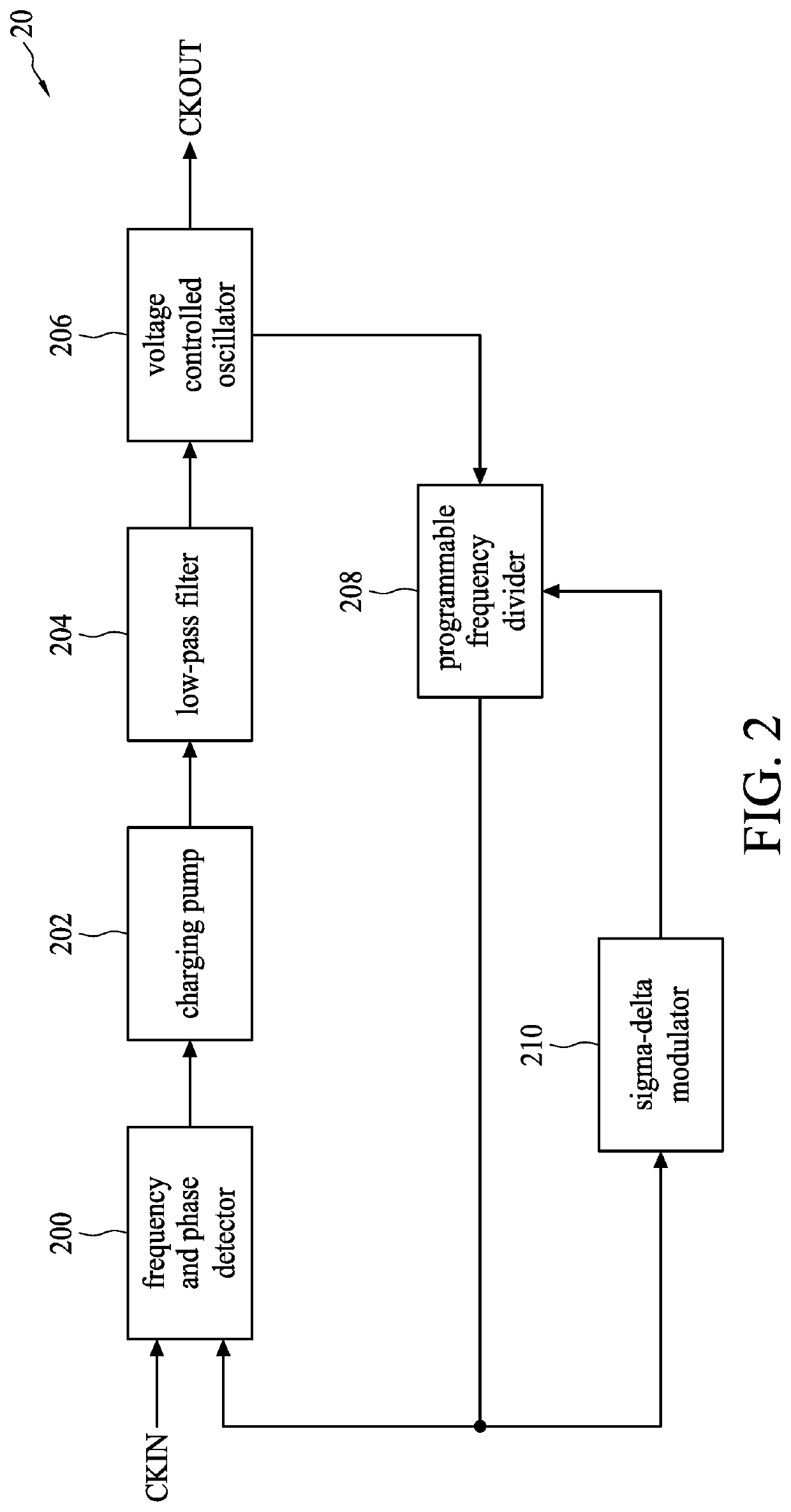
However, since the sigma-delta modulator 210 of the frequency combiner 20 would generate the quantization noise, one should reduce the loop bandwidth or enhance the resolution of the programmable frequency divider 208 to inhibit the quantization noise, wherein, reducing the loop bandwidth can be achieved by increasing the circuit area, whereas enhancing the resolution can be achieved by increasing the number of the output phase of the voltage controlled oscillator 206, thereby resulting in the generation of additional power consumptions.

Method used


Image

  • Frequency generator and method for generating frequency
  • Frequency generator and method for generating frequency
  • Frequency generator and method for generating frequency

Examples


Embodiment Construction

[0021]Purposes, technical solutions and advantages of the present disclosure are best understood from the following detailed description when read with the accompanying figures. It is noted that, embodiments provided herein are for discussing the present disclosure, and shall not be construed as limiting to the present disclosure. Further, it will be understood that when an element is referred to as being “connected to” or “coupled to” another element, it may be directly connected to or coupled to the other element, or intervening elements may be present.

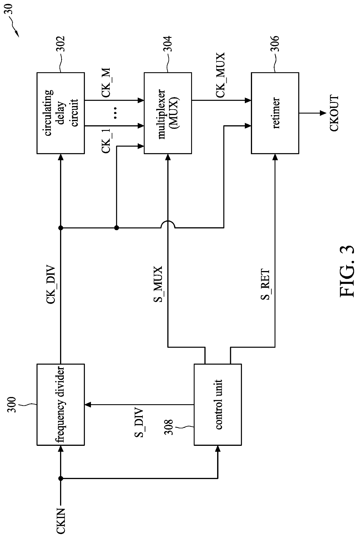
[0022]Reference is made to FIG. 3, which is a schematic diagram illustrating a frequency generator 30 according to one embodiment of the present disclosure. The frequency generator 30 includes a frequency divider 300, a circulating delay circuit 302, a multiplexer (MUX) 304, a retimer 306 and a control unit 308. The control unit 308 is configured to receive an input signal CKIN, so as to generate a divisor signal S_DIV, a phase sign...


PUM


Abstract

A frequency generator, includes a control unit, configured to receive an input signal to generate a divisor signal, a phase signal and a circulation signal; a frequency divider, configured to receive the input signal and perform an integer division to the input signal according to the divisor signal, so as to generate a frequency division signal; a circulating delay circuit, coupled to the frequency divider and configured to perform at least one circulating operation to the frequency division signal, and for each circulating operation, generate at least one phase delay signal; a first multiplexer, coupled to the circulating delay circuit and configured to select one signal from the frequency division signal and the at least one phase delay signal according to the phase signal, so as to generate a multiplexed signal; and a retimer, coupled to the first multiplexer and configured to generate an output signal.

Description

CROSS REFERENCE TO RELATED APPLICATIONS[0001]The present application is a continuation of international application No. PCT / CN2018 / 080993, filed on Mar. 29, 2018, of which is incorporated herein by reference in its entirety.TECHNICAL FIELD[0002]The present disclosure relates to a frequency generator, and more particular to a low-power open-loop fractional frequency generator.BACKGROUND[0003]Electronic system needs frequency signals with different frequencies so that it can be adapted to different operations or applications; considering the design and manufacturing cost, electronic systems often generate frequency signals with different frequencies according to the reference frequency signals.[0004]Generally, when there is a fractional-multiple relationship between the frequency of the input signal and the frequency of the output signal, a multiphase frequency generator and a frequency combiner are used to generate the desired output signal. Reference is made to FIG. 1, which is a sc...

Claims


Application Information

Patent Timeline
Patent Type & Authority Patents(United States)
IPC IPC(8): H03L7/08H03L7/181H03L7/099H03L7/193
CPCH03L7/099H03L7/0802H03L7/193H03L7/181H03K19/16G06F1/04
Inventor HUANG, YEN-YINCHANG, JUNG-YUHSU, MING-FENG
Owner SHENZHEN GOODIX TECH CO LTD
Learn More