
Cartridge device for lubricating a machine

a cartridge device and machine technology, applied in the direction of packaging, lubricant transfer, lubrication elements, etc., can solve the problems of collapsible reservoir from contracting or creasing, and it is not possible to simply reverse the orientation of the cartridge container, so as to eliminate the undesirable creasing behavior of the collapsible reservoir

Active Publication Date: 2020-05-26
POLY CLIP SYST
View PDF32 Cites 0 Cited by
  • Summary
  • Abstract
  • Description
  • Claims
  • Application Information

AI Technical Summary

Benefits of technology

The patent is about a lubricating device that can be easily replaced when the lubricant is used up. The device is made of metal, which can resist high temperatures and be easily cleaned or sterilized. It can be quickly and easily detached from the pneumatic system and refilled with a collapsible reservoir. The technical effect of this invention is to provide a more efficient and flexible lubricating system that can be easily maintained and replaced.

Problems solved by technology

This may prevent the collapsible reservoir from contracting or creasing due to the suction of the pump unit in a disadvantageous manner.
For instance, the collapsible reservoir may crease in such a way that an amount of lubricant cannot be sucked out of the collapsible reservoir by the pump unit.
In this case, in order to refill the cartridge device it is not possible to simply reverse the orientation of the cartridge container.

Method used


Image

  • Cartridge device for lubricating a machine
  • Cartridge device for lubricating a machine
  • Cartridge device for lubricating a machine

Examples


Embodiment Construction

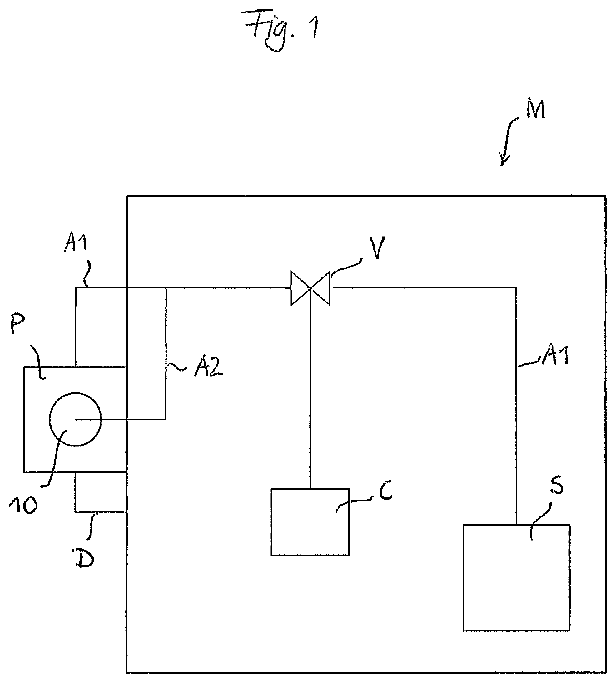
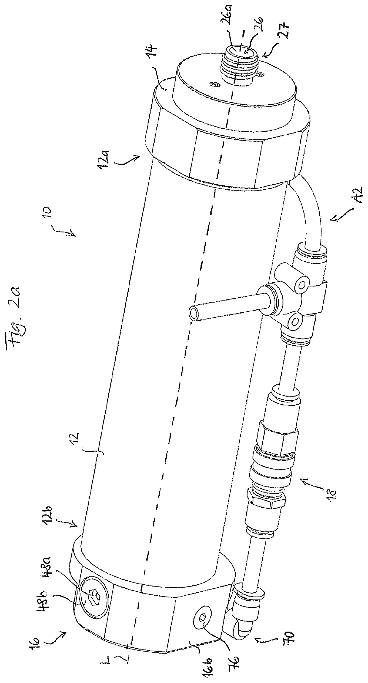
[0041]FIG. 1 schematically illustrates a machine M comprising a pneumatic system S connected via an air supply line A1 to a pump unit P to drive the same. Air supply line A1 may be pneumatically connected and disconnected from pneumatic system S by means of a valve V. Valve V may be controlled by a control unit C of machine M. When air supply line A1 is pneumatically connected to pump unit P by opening valve V, pump unit P is operated by the pressure provided by pneumatic system S. When air supply line A1 is disconnected from pump unit P by closing valve V, the supply of pressure from pneumatic system S and thus the operation of pump unit P stops. Pump unit P is connected to a cartridge device 10 as will be described in more detail below. Cartridge device 10 may be part of machine M or may be provided separately from machine M. Cartridge device 10 is provided with a supply of lubricant for lubricating machine M. By the operation of pump unit P, lubricant is delivered from cartridge ...


PUM


Abstract

The invention relates to a cartridge device for lubricating a machine, preferably a clipping machine, having a pneumatic system and a pump unit driven by the pneumatic system, the cartridge device comprising a cartridge container for accommodating a supply of lubricant having a longitudinal axis defining a longitudinal direction, wherein the cartridge container comprises a first end portion and a second end portion located opposite the first end portion in the longitudinal direction, and a first closure element for detachably coupling the first end portion of the cartridge container to a suction side of the pump unit, wherein the first closure element has a delivery opening for supplying lubricant contained within the cartridge container to the suction side of the pump unit. The invention is characterized in that the first closure element is detachably coupleable to the first end portion of the cartridge container, the first end portion of the cartridge container being configured so as to allow a collapsible reservoir containing the supply of lubricant to be inserted into and removed from the cartridge container.

Description

CROSS-REFERENCE TO RELATED APPLICATION[0001]The present application claims the benefit of priority of European Patent Application No. 16168435.2 filed May 4, 2016, the contents of which are incorporated herein by reference in their entirety.FIELD[0002]The present invention relates to a cartridge device and a method for lubricating a machine, preferably a clipping machine, having a pneumatic system and a pump unit driven by the pneumatic system. The present invention further relates to a lubricating device comprising the cartridge device, and to a machine comprising the lubricating device. Further, the present invention relates to a use of the cartridge device with such a machine and to a use of a collapsible reservoir with the cartridge device.BACKGROUND OF THE INVENTION[0003]More precisely, the invention relates to a cartridge device for lubricating a machine, preferably a clipping machine, having a pneumatic system and a pump unit driven by the pneumatic system, the cartridge devi...

Claims


Application Information

Patent Timeline
Patent Type & Authority Patents(United States)
IPC IPC(8): F16N19/00F16N11/10B65D83/00F16N7/14
CPCF16N11/10B65D83/0005F16N19/00F16N7/14F16N7/38F16N37/00F16N2037/006
Inventor MÜNKER, UDO
Owner POLY CLIP SYST
Learn More