
Magneto-caloric thermal diode assembly with an axially pinned magneto-caloric cylinder

a thermal diode and cylinder technology, applied in the field of heat pumps, can solve the problems of not operating at about forty-five percent or less of the maximum theoretical carnot cycle efficiency, the range of ambient temperatures over which certain refrigerant-based systems can operate may be impractical for certain locations, and the difficulty of practical and cost-competitive use of an mcm

Active Publication Date: 2020-05-12
HAIER US APPLIANCE SOLUTIONS INC
View PDF312 Cites 7 Cited by
  • Summary
  • Abstract
  • Description
  • Claims
  • Application Information

AI Technical Summary

Benefits of technology

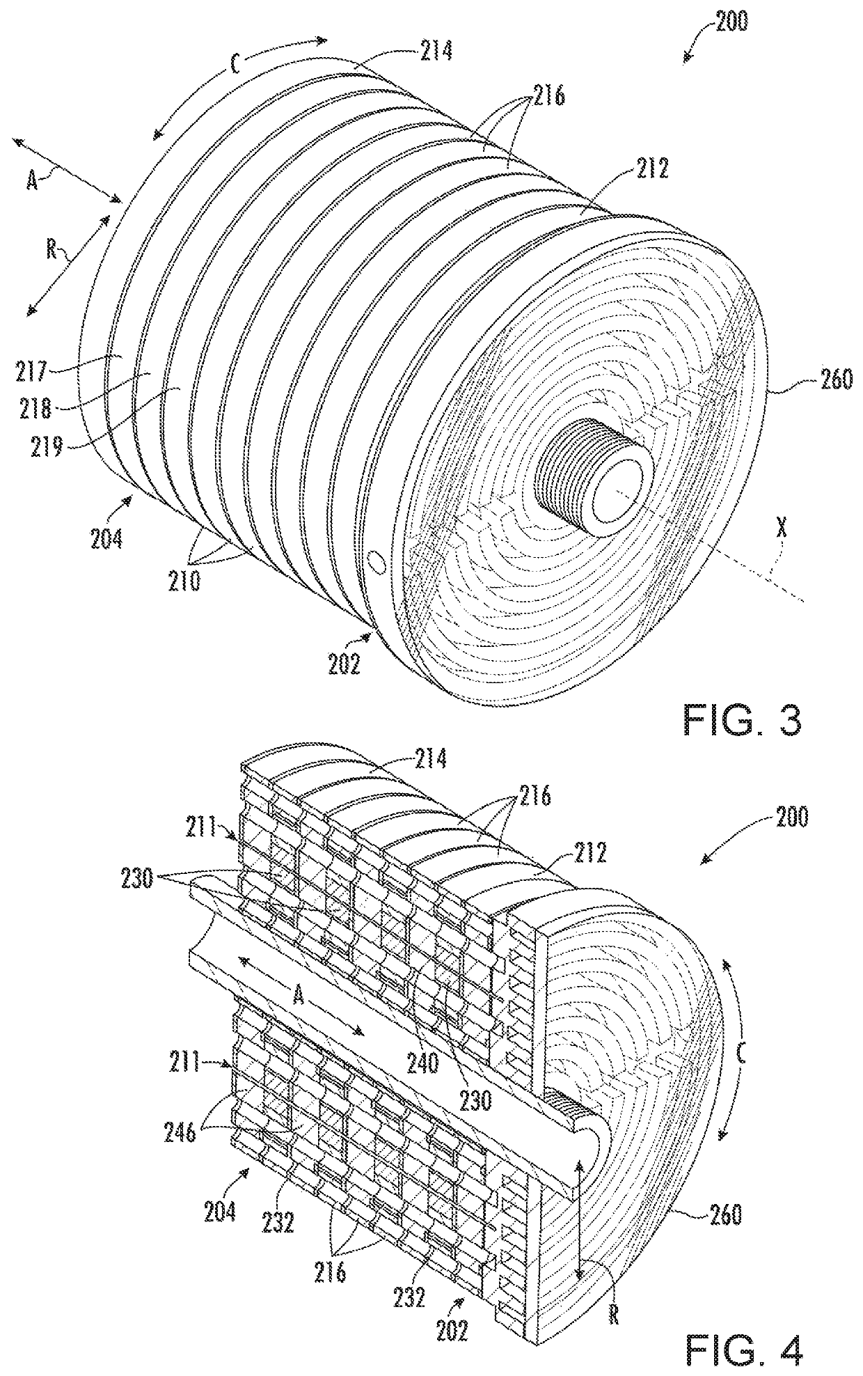
The invention is a magneto-caloric thermal diode assembly that includes a magneto-caloric cylinder with multiple magneto-caloric stages and insulation blocks. The magneto-caloric stages and insulation blocks are distributed sequentially along the cylinder's axial direction. The assembly also includes pins that extend between the magneto-caloric stages and insulation blocks. The assembly can rotate relative to the external environment. In a second embodiment, the cylinder includes a plurality of magneto-caloric stages and insulation blocks, with pins extending between them. The technical effects of the invention are improved heating and cooling of the assembly, achieved by the sequential distribution of magneto-caloric stages and insulation blocks, as well as the pins that connect them.

Problems solved by technology

While improvements have been made to such heat pump systems that rely on the compression of fluid refrigerant, at best such can still only operate at about forty-five percent or less of the maximum theoretical Carnot cycle efficiency.
The range of ambient temperatures over which certain refrigerant-based systems can operate may be impractical for certain locations.
Other challenges with heat pumps that use a fluid refrigerant exist as well.
Challenges exist to the practical and cost competitive use of an MCM, however.
Currently proposed equipment may require relatively large and expensive magnets, may be impractical for use in e.g., appliance refrigeration, and may not otherwise operate with enough efficiency to justify capital cost.

Method used


Image

  • Magneto-caloric thermal diode assembly with an axially pinned magneto-caloric cylinder
  • Magneto-caloric thermal diode assembly with an axially pinned magneto-caloric cylinder
  • Magneto-caloric thermal diode assembly with an axially pinned magneto-caloric cylinder

Examples


Embodiment Construction

[0027]Reference now will be made in detail to embodiments of the invention, one or more examples of which are illustrated in the drawings. Each example is provided by way of explanation of the invention, not limitation of the invention. In fact, it will be apparent to those skilled in the art that various modifications and variations can be made in the present invention without departing from the scope or spirit of the invention. For instance, features illustrated or described as part of one embodiment can be used with another embodiment to yield a still further embodiment. Thus, it is intended that the present invention covers such modifications and variations as come within the scope of the appended claims and their equivalents.

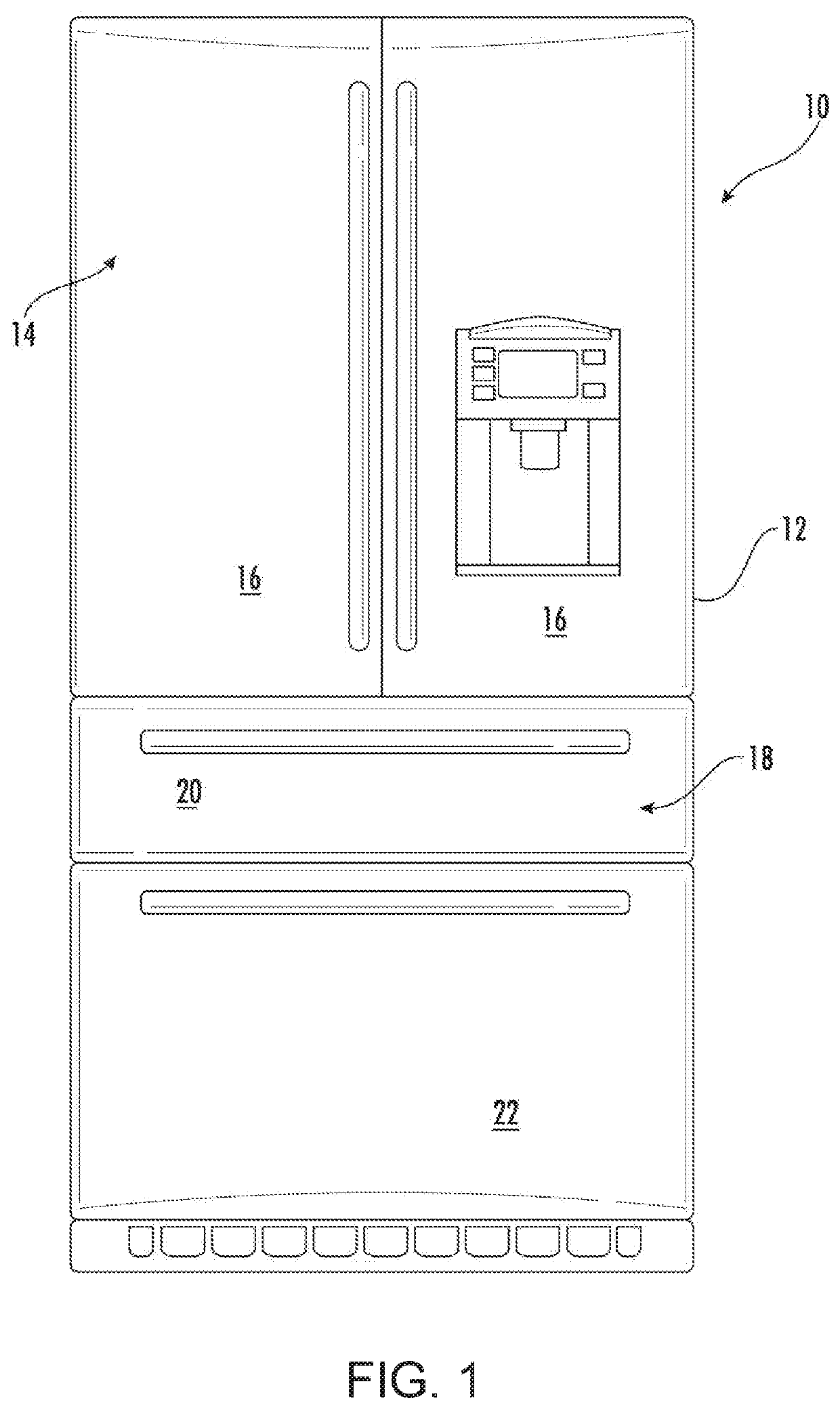
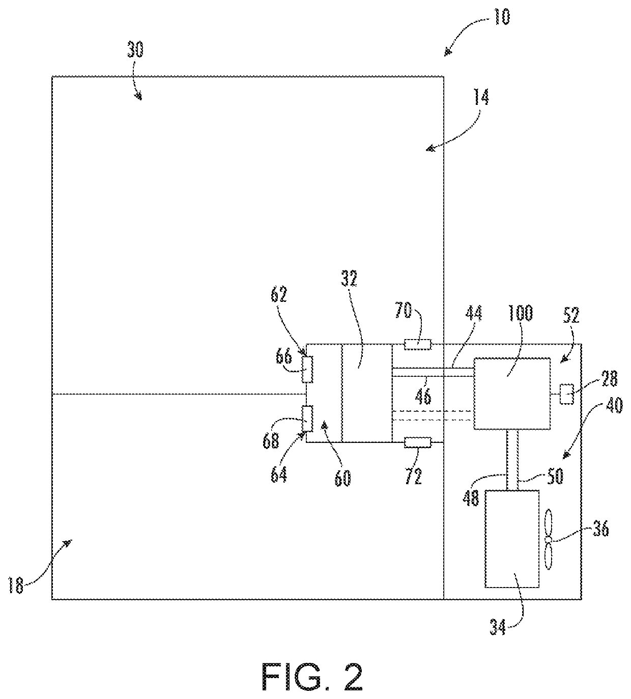
[0028]Referring now to FIG. 1, an exemplary embodiment of a refrigerator appliance 10 is depicted as an upright refrigerator having a cabinet or casing 12 that defines a number of internal storage compartments or chilled chambers. In particular, refrigerato...


PUM

PropertyMeasurementUnit
Curie temperatureaaaaaaaaaa
conductiveaaaaaaaaaa
thicknessaaaaaaaaaa

Abstract

A magneto-caloric thermal diode assembly includes a magneto-caloric cylinder with a plurality of magneto-caloric stages. Each of the plurality of magneto-caloric stages has a respective Curie temperature. The magneto-caloric cylinder also includes a plurality of insulation blocks and a plurality of pins. The plurality of magneto-caloric stages and the plurality of insulation blocks are distributed sequentially along an axial direction in the order of magneto-caloric stage then insulation block. One or more the plurality of pins extends along the axial direction between each magneto-caloric stage and a respective insulation block within the magneto-caloric cylinder.

Description

FIELD OF THE INVENTION[0001]The present subject matter relates generally to heat pumps, such as magneto-caloric heat pumps.BACKGROUND OF THE INVENTION[0002]Conventional refrigeration technology typically utilizes a heat pump that relies on compression and expansion of a fluid refrigerant to receive and reject heat in a cyclic manner so as to effect a desired temperature change or transfer heat energy from one location to another. This cycle can be used to receive heat from a refrigeration compartment and reject such heat to the environment or a location that is external to the compartment. Other applications include air conditioning of residential or commercial structures. A variety of different fluid refrigerants have been developed that can be used with the heat pump in such systems.[0003]While improvements have been made to such heat pump systems that rely on the compression of fluid refrigerant, at best such can still only operate at about forty-five percent or less of the maxim...

Claims


Application Information

Patent Timeline
Patent Type & Authority Patents(United States)
IPC IPC(8): F25B21/00H01L37/04F28D15/02F25D11/02H01F1/01H10N15/20
CPCF28D15/0275H01L37/04H01F1/012F25B21/00F25D11/02F25B2321/0022F25B2321/002F25B2321/0023F25D17/065F25D17/045Y02B30/00H10N15/20
Inventor SCHROEDER, MICHAEL GOODMAN
Owner HAIER US APPLIANCE SOLUTIONS INC
Learn More