
Biochip storage wells

a biochip and storage well technology, applied in the field of immunoassays, can solve the problems of fluid loss through vapour through the opening of the well cavity and subsequent contamination of the environment, lab equipment or a biochip analyser, incur an additional cost, etc., and achieve the effect of facilitating the sliding motion of the cap

Active Publication Date: 2020-05-12
NORTHERN BANK LTD
View PDF12 Cites 0 Cited by
  • Summary
  • Abstract
  • Description
  • Claims
  • Application Information

AI Technical Summary

Benefits of technology

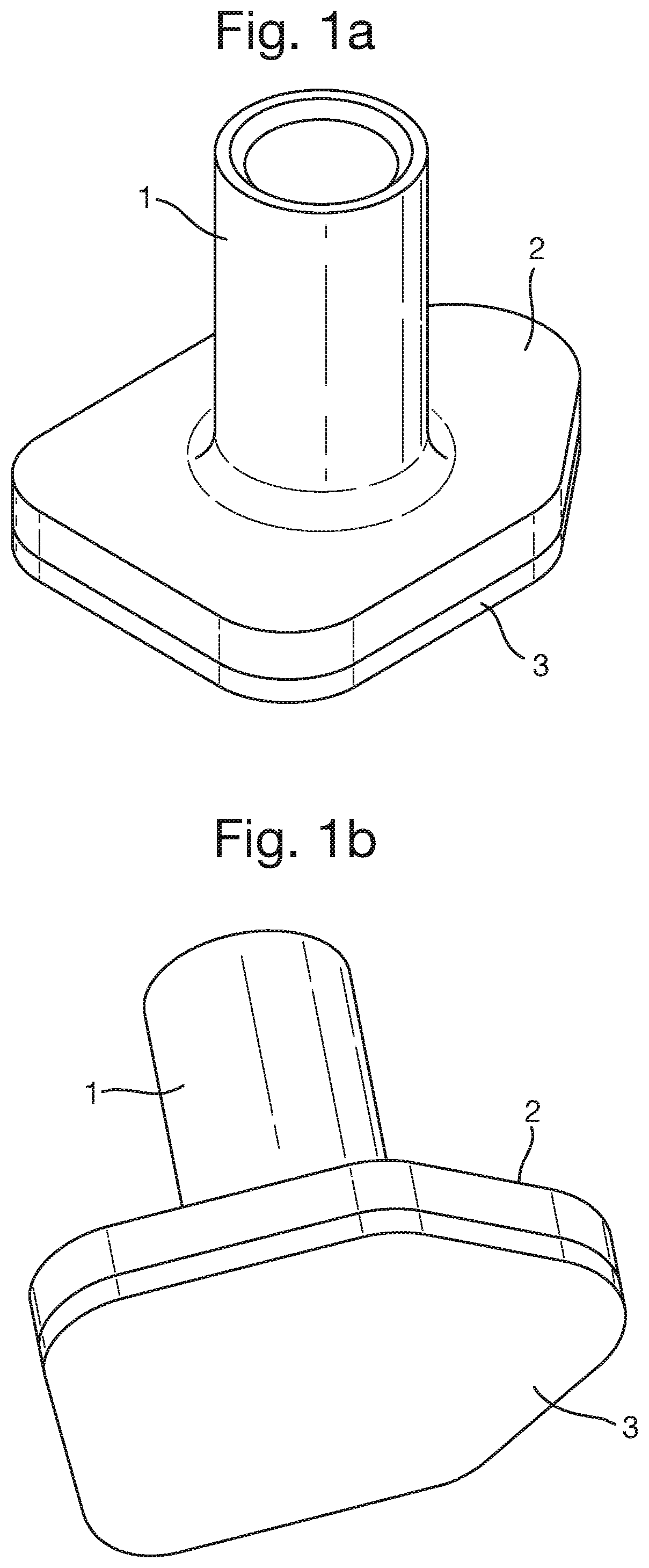
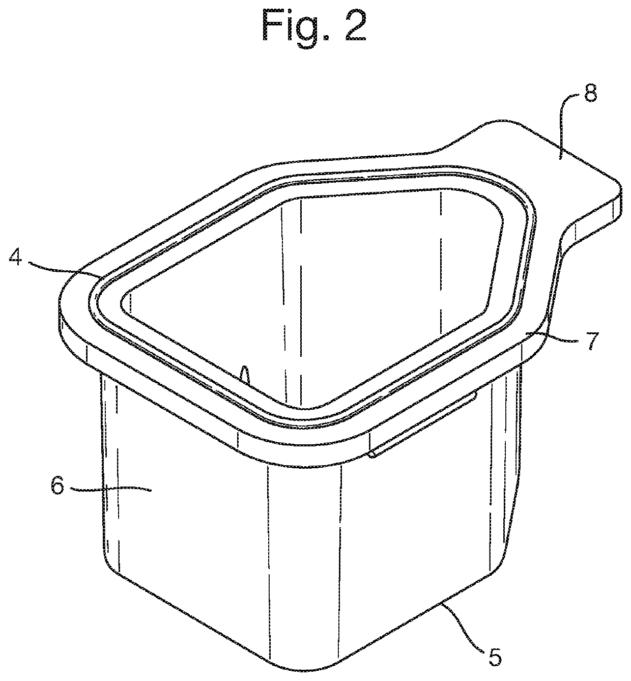
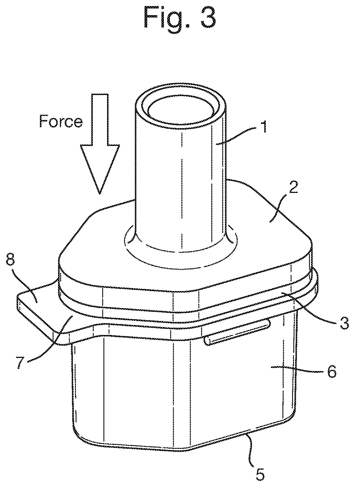
The present invention provides a cap for use with a receptacle such as an assay assembly comprising a biochip storage well and biochip. The cap forms a tight vapour-proof seal using a resilient sealant layer and the biochip storage well. The cap is clean, disposable, and does not contaminate the assay or reduce sensitivity of assays. The sealing process is simple and does not require complicated robotics. The cap can be opened and closed easily, and provides protection to the biochip during storage and manipulation. The technical effects of the invention are improved protection and preservation of the biochip, simplified and efficient sealing process, and easy handling of the cap.

Problems solved by technology

A problem with the assay assemblies described in the prior art is that the storage well should be sealed in order to reduce vapour loss during the heating stage of the immunoassay.
When the well is heated during the run of an assay, depending on the temperature, there is the risk of fluid loss via vapour through the opening of the well cavity and the subsequent contamination of the environment, lab equipment or a biochip analyser.
If the vapour loss were to be corrected for by adding additional fluid, this would incur an additional cost, and there would still be risk of contamination of the environment.
Firstly, oil is often used to form a seal on top of the fluid during heating.
The oil would also coat the surface of the biochip if the fluid were removed from the well as part of the assay, or reduce sensitivity of detection by forming a layer between the camera and the biochip.
Further, applying the foil as part of an automated process is a complicated, costly and space consuming task for a biochip analyser to perform and so is undesirable.
However, such caps require complicated robotics to form a seal.
Further, the thread in a screw cap is not vapour proof, resulting in some evaporation and loss of fluid through the thread at high temperatures or during prolonged time periods.
Additionally, plug caps have an inherent risk of aggressive depression at high liquid temperatures, causing a sudden jerking motion which can result in droplets of fluid escaping.
Therefore, both screw caps and plug caps harbour risks of contamination where hazardous fluids are present.

Method used


Image

  • Biochip storage wells
  • Biochip storage wells
  • Biochip storage wells

Examples


Embodiment Construction

[0057]The invention will now be described in relation to the following non-limiting examples. The amount of evaporation occurring in an assay assembly comprising a cap according to the first embodiment of the present invention and biochip storage well as illustrated in FIG. 2 was determined, in order to investigate the vapour-proof seal between the resilient sealant layer and knife-edge interface. A force of 50 N was applied to the cap to act as the clamping force.

[0058]The test method used to determine the % of evaporation was as follows;[0059]Heat wells to 60° C. for 1 hour[0060]Place 550 μl of deionised water into the wells[0061]Weigh the wells before and after test[0062]Well caps should be clamped at 50 N

[0063]Table 1 shows the results for the above method when testing a nitrile sealant layer of 1 mm. The cap according to the present invention, comprising a 1 mm nitrile sealant layer was placed onto the storage well of FIG. 2 containing 550 μl of deionised water. A force of 50 N...


PUM

PropertyMeasurementUnit
thicknessaaaaaaaaaa
thicknessaaaaaaaaaa
thicknessaaaaaaaaaa

Abstract

The present invention is directed to a cap for a biochip storage well. The cap comprises a resilient sealant layer capable, under the application of pressure, of forming a vapour-proof seal with a line contact interface formation extending around the perimeter of a biochip storage well.An assay assembly comprising the cap of the invention and a biochip storage is disclosed. Methods of sealing a biochip storage well using a cap of the invention are also disclosed.

Description

CROSS REFERENCE TO RELATED APPLICATIONS[0001]This application is a U.S. National Stage Application filed under 35 U.S.C. § 371 and claims the benefit of International Application No. PCT / GB2015 / 053983, filed Dec. 14, 2015, which application claims priority to Great Britain Application No. 1422231.9, filed Dec. 15, 2014, the disclosure of which are incorporated herein by reference.FILED OF THE INVENTION[0002]The invention is directed to improvements relating to biochip storage wells, specifically in the field of assay devices and assemblies.BACKGROUND OF THE INVENTION[0003]Assay devices in the form of biochips are well known in the field of immunoassays. Such biochips are often placed in storage wells and are deposited with an array of localised reactive sites containing potentially many different reactive species, for example, different proteins. These reactive species react with a respective different analyte in a sample supplied to the chip. Following removal of the unbonded sampl...

Claims


Application Information

Patent Timeline
Patent Type & Authority Patents(United States)
IPC IPC(8): B01L9/00C12M1/00B01L3/00B65B7/28
CPCB65B7/2871B01L3/508B01L9/52C12M23/38B01L2300/0636B01L2300/047B01L2300/045B01L2300/044B01L2300/0832B01L2300/042B01L2200/142B01L2300/161B01L2200/0689
Inventor JACKSON, STUARTMCCONNELL, IVANLAMONT, JOHNFITZGERALD, PETERWHARRY, MARC
Owner NORTHERN BANK LTD
Learn More