
Flow rate control device

a flow controller and flow rate technology, applied in the direction of diaphragm valves, instruments, valve housings, etc., can solve the problems of unstable flow control and difficulty in determining the optimum value of the coefficient to be changed, and achieve the effect of reducing the pressure oscillation that has occurred on the upstream side of the flow controller and in the control valve, ensuring the pressure fluctuation suppressing effect of the expansion chamber, and increasing the volume of the expansion chamber

Active Publication Date: 2020-05-05
FUJIKIN INC
View PDF50 Cites 0 Cited by
  • Summary
  • Abstract
  • Description
  • Claims
  • Application Information

AI Technical Summary

Benefits of technology

This configuration collectively reduces pressure oscillations, ensures effective suppression of fluctuations even for high-flow fluids, enhances maintainability by allowing easy replacement of components without disassembling connected pipes, and prevents pressure drop increases.

Problems solved by technology

The hunting of the detected pressure makes the flow control unstable.
However, with such software-wise measures, it is not easy to derive the optimum value of the coefficient to be changed.

Method used


Image

  • Flow rate control device
  • Flow rate control device
  • Flow rate control device

Examples


examples

[0076]Hereinafter, the present invention will be described in further detail with reference to examples and comparative examples. However, the present invention is not limited to these examples.

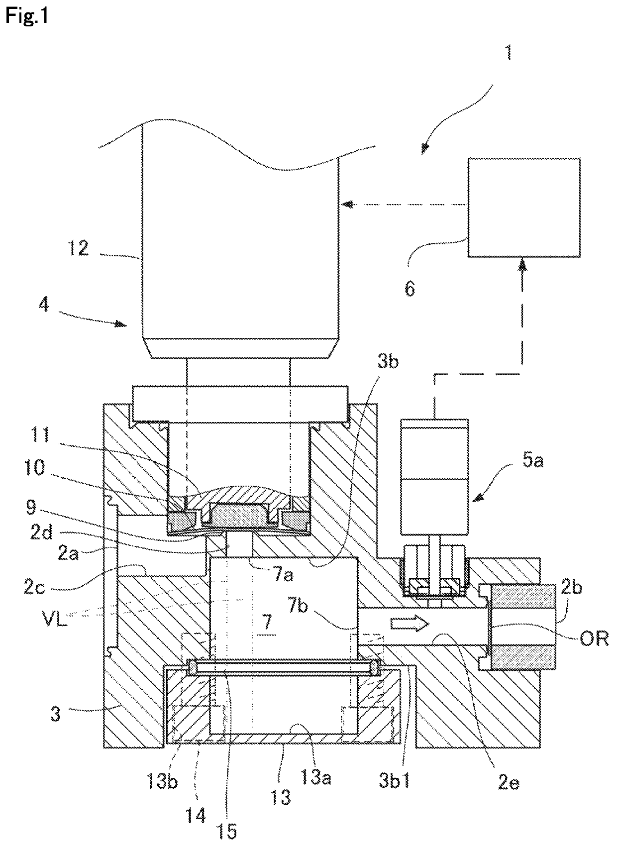
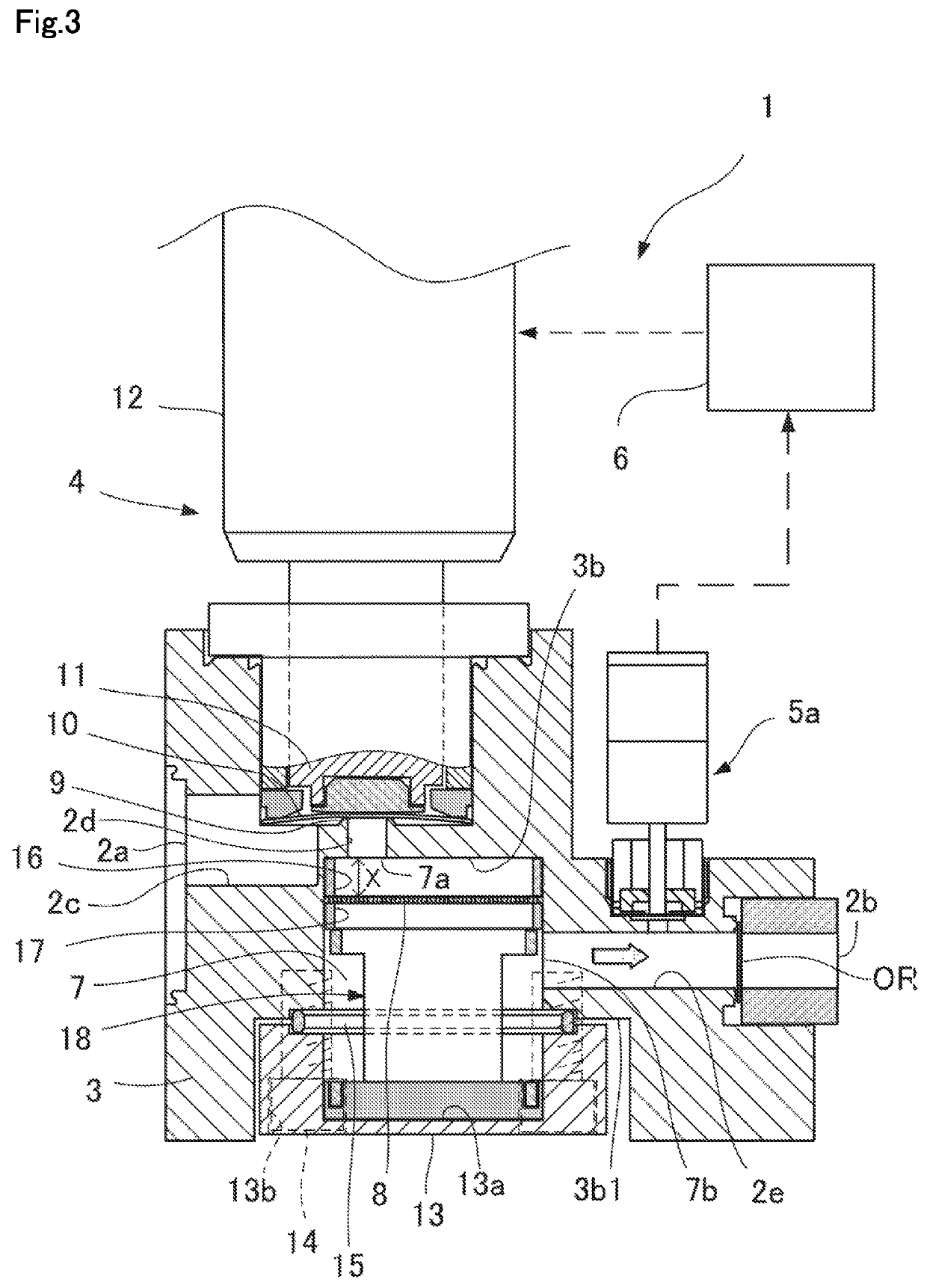
[0077]In Example 1, a flow controller having the configuration of FIG. 1 was used. In Example 2, the flow controller shown in FIG. 3 was used. As the distribution plate of Example 2, a distribution plate made of stainless steel shaped as shown in FIG. 7 having a pore size of 1 mm, 37 holes, a pitch of 2 mm, a thickness of 0.5 mm, and an aperture ratio of 22.7% was used. In Examples 1 and 2, the internal volume of the flow passage from the valve seat 9 of the control valve 4 to the restriction part OR was about 5 cc.

[0078]In the comparative example, the pressure-type flow controller shown in FIG. 11 was used. In the comparative example, the internal volume of the flow passage from the valve seat 9 of the control valve 4 to the restriction part OR was 0.6 cc.

[0079]Both in the examples and compa...


PUM


Abstract

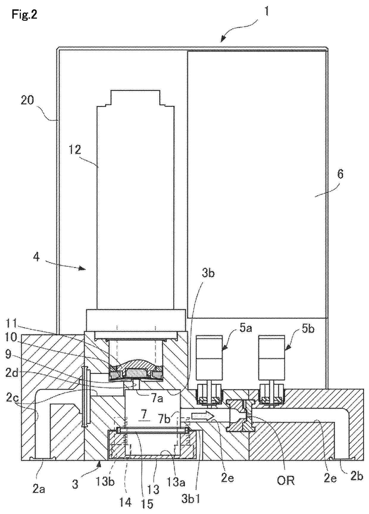
The flow controller according to the present invention includes: a control valve; a first flow passage provided on the downstream side of the control valve; a second flow passage; and an expansion chamber provided between the first flow passage and the second flow passage. The second flow passage is provided in a position that is not on the extension of the first flow passage.

Description

TECHNICAL FIELD[0001]The present invention relates to a flow controller.BACKGROUND ART[0002]Conventionally, as shown in FIG. 11, a flow controller (also referred to as “pressure-type flow controller”) including a main body block 3 having formed therein a flow passage 2 that connects between a gas inlet 2a and a gas outlet 2b, a restriction part OR interposed in the flow passage 2, a control valve 4 interposed in the flow passage 2 upstream from the restriction part OR, a first pressure detector 5a that detects the pressure in the flow passage 2 between the control valve 4 and the restriction part OR, and a controller 6 that controls the control valve 4 so as to achieve a predetermined flow rate based on a value detected by the first pressure detector 5a is known (Patent Document 1, etc.).[0003]This control utilizes the principle that when a so-called critical expansion condition of (P1 / P2) about 2 is maintained between an upstream pressure (P1) of the restriction part OR and a downs...

Claims


Application Information

Patent Timeline
Patent Type & Authority Patents(United States)
IPC IPC(8): F16K27/02F16K7/14F16K7/16G05D7/06
CPCG05D7/0635F16K27/0236F16K7/14F16K7/16Y10T137/7761
Inventor HIRAI, TORUMORISAKI, KAZUYUKIHIRATA, KAORUNISHINO, KOUJIIKEDA, NOBUKAZU
Owner FUJIKIN INC
Learn More