
Refuse collection vehicle and system therefor

a technology for removing refuse and a collection vehicle, which is applied in the direction of refuse vehicles, lifting devices, safety devices for lifting equipment, etc., can solve the problems of real danger of accidental injury to people, the movement of the lifting mechanism of the bin, and in particular the front loader lifting mechanism, so as to avoid abrupt discontinuities in the external shaping and maximise the effect of monitoring area

Active Publication Date: 2020-04-28
BUCHER MUNICIPAL PTY LTD
View PDF10 Cites 5 Cited by
  • Summary
  • Abstract
  • Description
  • Claims
  • Application Information

AI Technical Summary

Benefits of technology

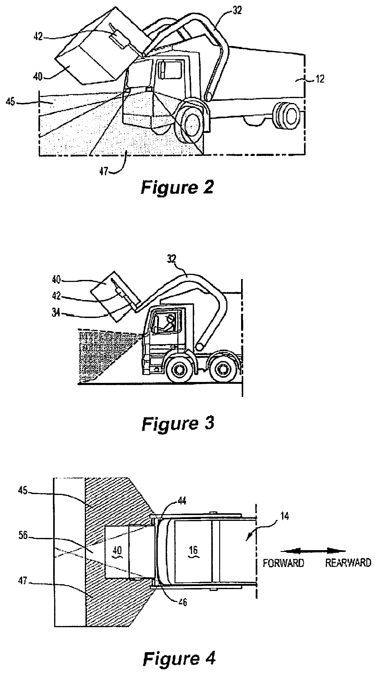
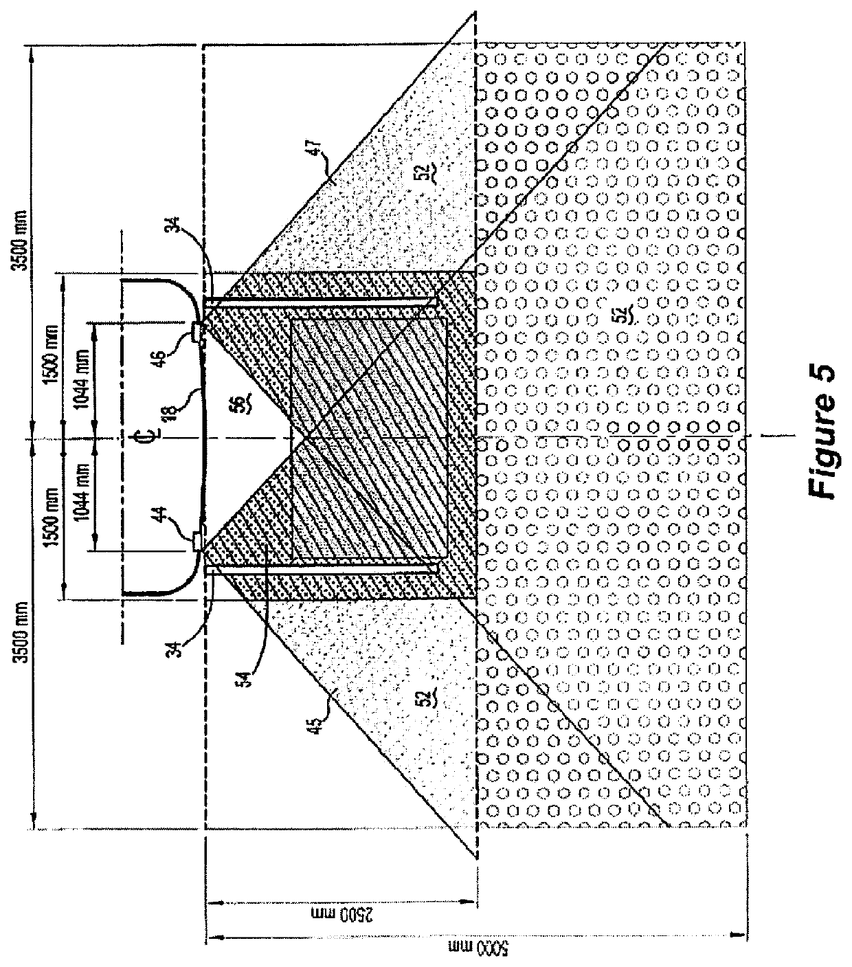
[0012]This arrangement allows the sensors to be mounted facing substantially in the forward direction, while maximising the field of view and hence the protection provided. By way of example, in comparison to other systems, the field of view is advantageously provided under arms of the lifting mechanism, enhancing the protection provided.
[0128]Such a system can provide excellent coverage of substantially the whole risk area in front of the vehicle, minimising any blind spots between sensors and therefore enabling a very high degree of operation safety.

Problems solved by technology

The movement of a bin lifting mechanism, and in particular a front loader lifting mechanism, can be a relatively complex and sometimes dangerous operation, particularly for any person or object in the vicinity.
There is a very real danger of accidental injury to a person who may pass in front of the vehicle during the bin lowering operation, and indeed such accidents have happened in recent years.

Method used


Image

  • Refuse collection vehicle and system therefor
  • Refuse collection vehicle and system therefor
  • Refuse collection vehicle and system therefor

Examples


Embodiment Construction

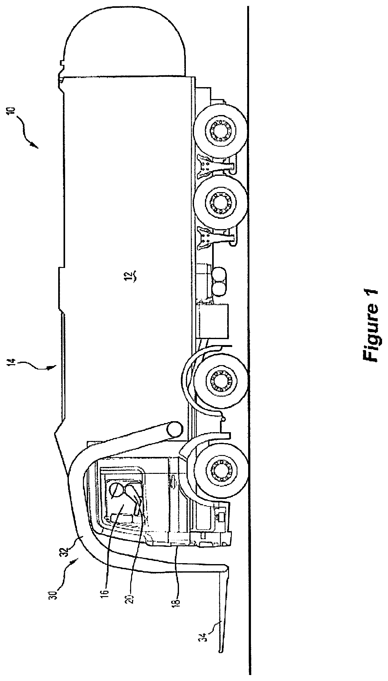
[0143]The refuse collection vehicle 10 of FIG. 1 includes a refuse storage body 12 and a cabin 16 at the front. Towards its forward end, refuse storage body 12 has a top opening 14, accessible by way of an opening hatch or door(s).

[0144]The front panel of cabin 16 is shown at 18, and a vehicle driver / operator is shown at 20.

[0145]A lifting mechanism 30 provides the means by which refuse bins can be engaged, lifted, raised and bought over the top of cabin 16 to be emptied into refuse storage body 12 by way of opening 14. Lifting mechanism 30 operates under control of a lifting control system operated by operator 20 manipulating command controls in cabin 16, eg. by moving a control joystick or other suitable interface means.

[0146]The lifting system comprises a pair of lifting arms 32, each pivotally connected to a side of the lower front part of the vehicle body front, and a pair of lifting forks 34. The movement of lifting arms 32 and lifting forks 34 is realised by operation of hydr...


PUM


Abstract

The invention provides a safety system for use with a refuse collection vehicle having a refuse storage body and a front cabin, the system operating to detect the presence of an object or person in the vicinity of the vehicle and communicate with a lifting operation system. The vehicle has a lifting mechanism for engagement with a refuse bin, the lifting operation system operable to move the lifting mechanism between a lowered position at which the bin is on the ground in front of the vehicle and a raised position for discharge of the bin contents into the interior of the refuse storage body. The safety system including one or more sensors able to monitor an area in the vicinity of the vehicle where the lifting mechanism lifts and lowers bins and a controller operative to receive input data from said at least two sensors and process said data to determine the presence of an object or person, the controller operative to control functioning of the lifting operation system in accordance with the determination by the controller. The invention further provides a vehicle incorporating such a safety system, such as a front loading refuse collection vehicle.

Description

FIELD OF THE INVENTION[0001]The present invention relates to refuse collection vehicles. In particular, the invention has application to front-end loading refuse collection vehicles, and systems for use with such vehicles, however it also has applications to other types of refuse collection vehicles, including side loading refuse collection vehicles.BACKGROUND OF THE INVENTION[0002]Several different general types of refuse collection vehicles are commonly used in collecting refuse. Front-end loading refuse collection vehicles, or ‘front loader vehicles’, are generally used for collecting refuse from larger or commercial sites, such as office buildings, schools, shops, factories, hospitals, etc. In this type of operation, the refuse is collected in a large bin, which is then emptied by the front loader vehicle. The vehicle is equipped towards its front end with a hydraulically-driven lifting mechanism, comprising lifting arms and fork arms. The vehicle driver / operator positions the v...

Claims


Application Information

Patent Timeline
Patent Type & Authority Patents(United States)
IPC IPC(8): B66F9/19B65F3/04B60P1/50B65F3/00B66F17/00B65F3/02
CPCB65F3/00B65F3/041B65F2003/0279
Inventor BUTCHER, EDWARDCATALDO, STEVENCLARKE, BRADLEY
Owner BUCHER MUNICIPAL PTY LTD
Learn More