Sensing method of fingerprint sensor

a fingerprint sensor and sensing technology, applied in the field of sensing methods, can solve the problems of large transmission impedance, difficult to determine and process the sensed capacitance, and increase the number of steps in the manufacturing process, so as to reduce the scan time and power consumption of the fingerprint sensor, increase and the effect of increasing the area of the sensing pixels

Active Publication Date: 2020-04-21
AU OPTRONICS CORP
View PDF7 Cites 0 Cited by
  • Summary
  • Abstract
  • Description
  • Claims
  • Application Information

AI Technical Summary

Benefits of technology

[0005]The disclosure provides a sensing method of a fingerprint sensor to increase scan resolution of the fingerprint sensor through self-capacitance sensing and mutual capacitance sensing. In the method, according to the required resolution of an identification requirement, it can be determined to perform the self-capacitance sensing on sensing pixels of the fingerprint sensor or perform the self-capacitance sensing and the mutual capacitance sensing sequentially.
[0007]In view of the above, in the sensing method of the fingerprint sensor provided in the embodiments of the disclosure, whether to perform the self-capacitance sensing on sensing pixels of the fingerprint sensor or perform the self-capacitance sensing and the mutual capacitance sensing sequentially may be determined according to the required resolution of an identification requirement, so as to adjust the scan time of the fingerprint sensor according to the identification requirement. Thereby, the identification requirement may be satisfied, and the scan time and the power consumption of the fingerprint sensor may be reduced. Furthermore, combining the self-capacitance sensing and the mutual capacitance sensing allows the increase in the area of the sensing pixels. The larger the area of the sensing pixels, the more sensitive of the sensing, and the greater the intensity of receiving signals.

Problems solved by technology

As such, it is difficult to determine and process the sensed capacitances.
In the conventional fingerprint sensor, the need to increase the area of the sensing (receiving) electrode may result in the compromise that the area of the transmission electrode is far smaller than the area of the sensing (receiving) electrode, and thus the transmission impedance is large.
However, manufacturing costs are also increased together with the increased number of steps in the manufacturing process.

Method used


Image

  • Sensing method of fingerprint sensor
  • Sensing method of fingerprint sensor
  • Sensing method of fingerprint sensor

Examples


Embodiment Construction

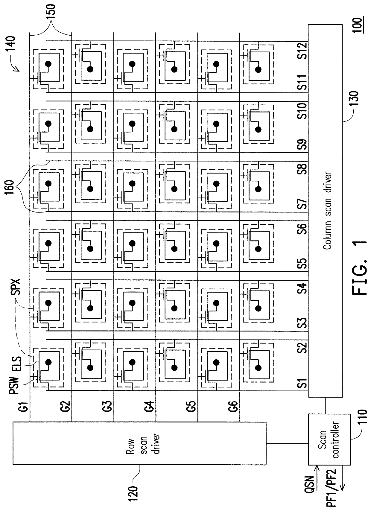
[0015]FIG. 1 is a schematic view illustrating a system of a fingerprint sensor according to an embodiment of the disclosure. With reference to FIG. 1, in the present embodiment, the fingerprint sensor 100 includes a scan controller 110, a row scan driver 120, a column scan driver 130, a sensing pixel array 140, a plurality of gate lines 150, and a plurality of source lines 160. The sensing pixel array 140 includes a plurality of sensing pixels SPX arranged in an array, e.g., a 6×6 sensing pixel array; however, the disclosure should not be limited thereto. Each of the sensing pixels SPX has a switch transistor PSW and a sensing electrode ELS. A gate of the switch transistor PSW is coupled to the corresponding gate line 150, a drain of the switch transistor PSW is coupled to the corresponding source line 160, and a source of the switch transistor PSW is coupled to the sensing electrode ELS. If the sensing pixel array 140 is observed from its upper-left corner as the reference point, t...


PUM


Abstract

A sensing method of a fingerprint sensor is provided. The fingerprint sensor includes a plurality of sensing pixels arranged in an array, and the sensing pixels respectively have a sensing electrode. The sensing method includes following steps. A required resolution of an identification requirement is determined; here, the identification requirement is received by the fingerprint sensor. If the number of pixels of the required resolution is less than or equal to the number of the sensing pixels, self-capacitance sensing is performed on the sensing pixels to provide a first fingerprint pattern. If the number of pixels of the required resolution is greater than the number of the sensing pixels, the self-capacitance sensing and mutual capacitance sensing are performed on the sensing pixels to provide a second fingerprint pattern.

Description

CROSS-REFERENCE TO RELATED APPLICATION[0001]This application claims the priority benefit of Taiwan application serial no. 106126161, filed on Aug. 3, 2017. The entirety of the above-mentioned patent application is hereby incorporated by reference herein and made a part of this specification.FIELD OF THE DISCLOSURE[0002]The disclosure relates to a sensing method and more particularly relates to a sensing method of a fingerprint sensor.DESCRIPTION OF RELATED ART[0003]A fingerprint sensor requires a certain level of resolution, whereby the area occupied by a sensing PAD is limited, and capacitances sensed by fingers are less accordingly. As such, it is difficult to determine and process the sensed capacitances. The area of the sensing electrode may be further reduced since an active fingerprint sensor is required to provide radio frequency signals.[0004]In the conventional fingerprint sensor, the need to increase the area of the sensing (receiving) electrode may result in the compromis...

Claims


Application Information

Patent Timeline
Patent Type & Authority Patents(United States)
IPC IPC(8): G06K9/00
CPCG06K9/0002G06V40/1306
Inventor LIN, WU-WEILO, JUI-CHI
Owner AU OPTRONICS CORP
Why Eureka
Try Eureka