Object tracking method and device based on laser scanning

A laser scanning and object tracking technology, applied in the field of laser scanning, can solve the problems of inability to track obstacles in time, poor obstacle tracking accuracy, etc.

Active Publication Date: 2021-04-06
BEIJING WANJI TECH
View PDF11 Cites 0 Cited by
  • Summary
  • Abstract
  • Description
  • Claims
  • Application Information

AI Technical Summary

Problems solved by technology

However, in the prior art, the scanning range and scanning resolution of the laser signal transmitting unit are usually fixed, so that the laser signal transmitting unit needs to scan the entire area in each scanning cycle to determine the position of the obstacle. As a result, obstacles cannot be tracked in time, resulting in poor tracking accuracy of obstacles

Method used


Image

  • Object tracking method and device based on laser scanning
  • Object tracking method and device based on laser scanning
  • Object tracking method and device based on laser scanning

Examples


Embodiment Construction

[0128] In order to make the purpose, technical solutions and advantages of the embodiments of the present invention clearer, the technical solutions in the embodiments of the present invention will be clearly and completely described below in conjunction with the drawings in the embodiments of the present invention. Obviously, the described embodiments It is a part of embodiments of the present invention, but not all embodiments. Based on the embodiments of the present invention, all other embodiments obtained by persons of ordinary skill in the art without making creative efforts belong to the protection scope of the present invention.

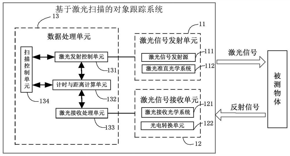
[0129] figure 1 A structural diagram of an object tracking system based on laser scanning provided by an embodiment of the present invention. See figure 1 , including a laser signal transmitting unit 11 , a laser signal receiving unit 12 and a data processing unit 13 . Optionally, the laser signal transmitting unit 11 includes a laser sign...


PUM


Abstract

An embodiment of the present invention provides an object tracking method and device based on laser scanning, the method includes: performing laser scanning according to a first rule in at least one first scanning cycle until an obstacle is scanned within a preset scanning range, Determine the first position information set of the obstacle, the scanning resolution in the first rule is the first scanning resolution, and the scanning range in the first rule is the preset scanning range; perform laser scanning according to the second rule in the second scanning cycle , determine the second set of position information of the obstacle, determine the next scanning period of the second scanning period as the new first scanning period, the scanning resolution in the second rule is the second scanning resolution, and the second scanning resolution Higher than the first scanning resolution; according to the first set of position information and the second set of position information, track information of the obstacle is determined. Used to improve the accuracy of tracking obstacles.

Description

technical field [0001] Embodiments of the present invention relate to the technical field of laser scanning, and in particular, to a laser scanning-based object tracking method and device. Background technique [0002] At present, with the continuous development of laser scanning technology, functions such as object positioning and tracking can be realized through laser scanning technology. [0003] In the prior art, when laser scanning is required, the laser signal emitting unit is usually installed on the motor, and the laser signal emitting unit can emit laser light at different angles under the drive of the motor, so that the laser signal emitting unit can be in the Laser scanning is performed in a certain area, and by scanning a certain area, it is determined whether there is an obstacle in the area or the obstacle is tracked. However, in the prior art, the scanning range and scanning resolution of the laser signal transmitting unit are usually fixed, so that the laser...

Claims


Application Information

Patent Timeline
Patent Type & Authority Patents(China)
IPC IPC(8): G01S17/93
CPCG01S17/93
Inventor 张国伟徐洋时也王庆飞
Owner BEIJING WANJI TECH
Why Eureka
Try Eureka