
Motion sensing cable for tracking customer interaction with devices

a technology of motion sensing and customer interaction, which is applied in the direction of instruments, burglar alarm mechanical actuation, transportation and packaging, etc., can solve the problems of reducing the charging signal delivered to the electronic device, and the device is not fully operational while being charged,

Active Publication Date: 2020-04-07
MOBILE TECH
View PDF397 Cites 0 Cited by
  • Summary
  • Abstract
  • Description
  • Claims
  • Application Information

AI Technical Summary

Benefits of technology

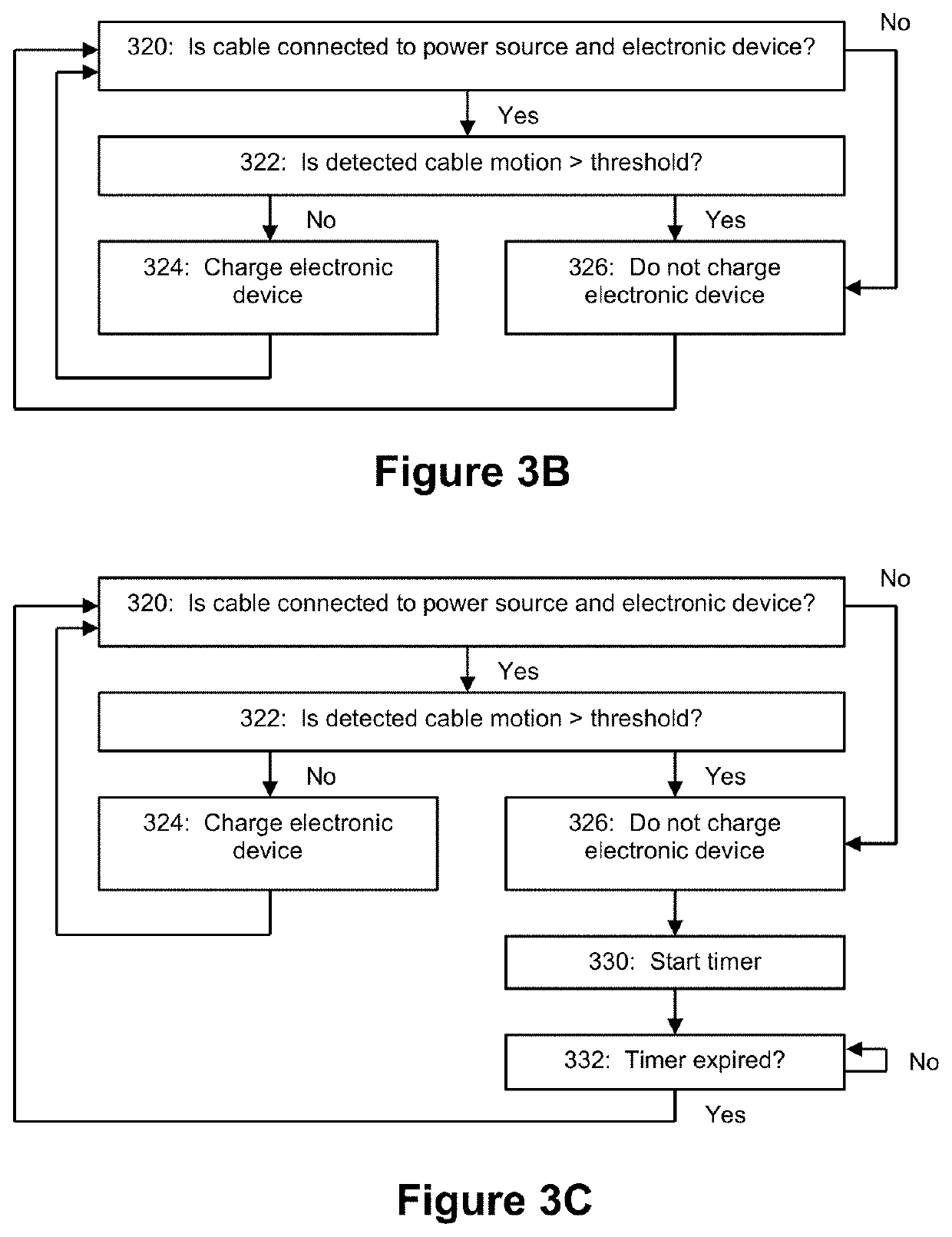
The patent describes a technology that controls the charging of electronic devices using a motion sensor. By detecting movement of the charging cable, the technology can reduce the charging signal sent to the device, which can help prevent battery overload and extend battery life. This technology can be used with various electronic devices such as smartphones and tablets.

Problems solved by technology

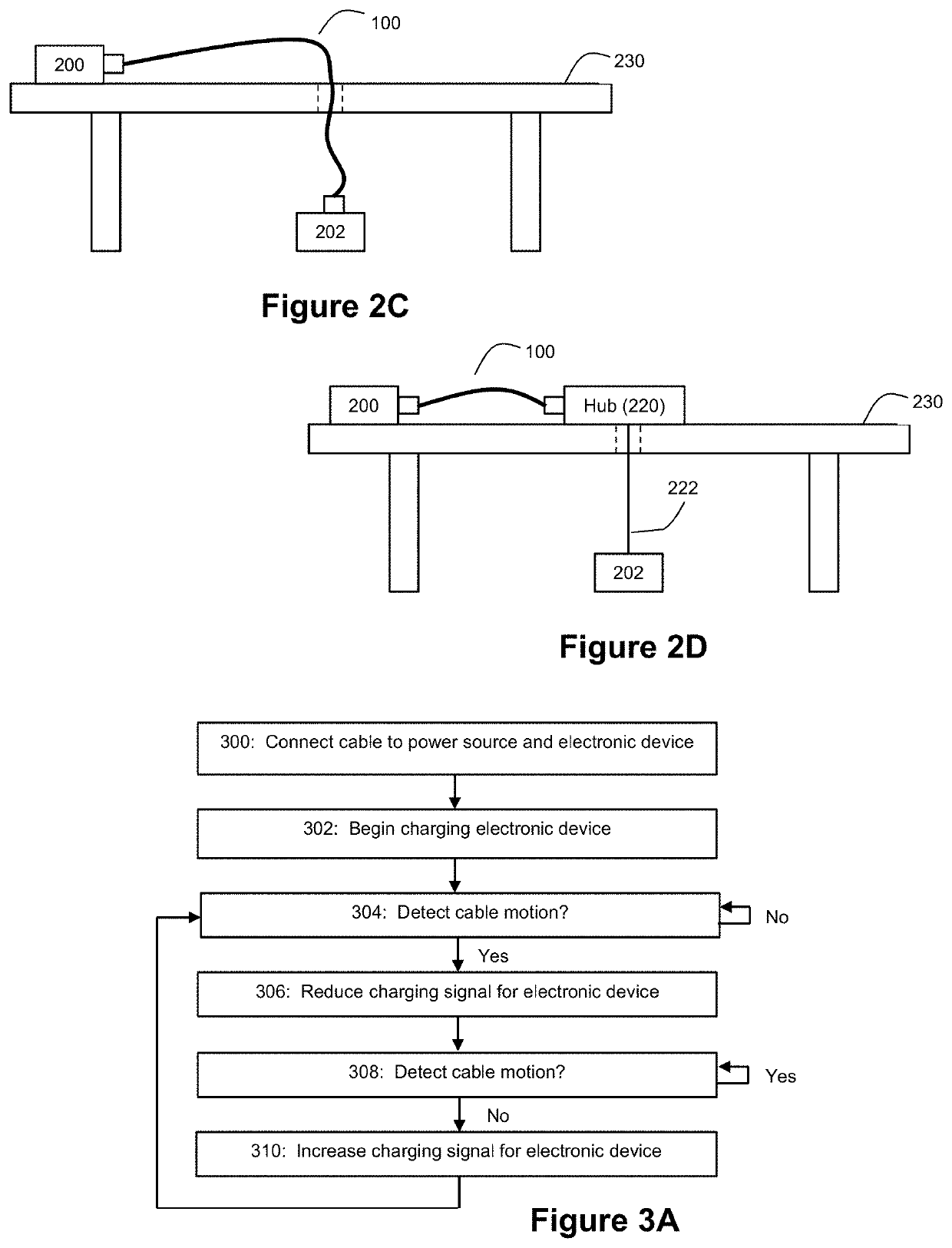
Thus, if a user were to lift the electronic device connected to the cable, this would cause the cable to reduce the charging signal delivered to the electronic device.
This creates a challenge, however, for devices that are not fully operational while being charged because the devices nevertheless need to be charged so that the device has sufficient power to be operational while it is on display.
While no customers are interacting with the electronic device, it is expected that the electronic device will be at rest, and the motion sensing cable will not detect any motion.

Method used


Image

  • Motion sensing cable for tracking customer interaction with devices
  • Motion sensing cable for tracking customer interaction with devices
  • Motion sensing cable for tracking customer interaction with devices

Examples


Embodiment Construction

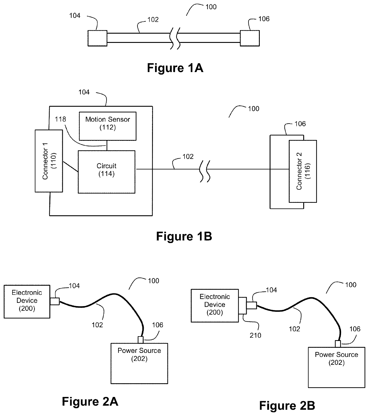
[0019]FIG. 1A shows an example motion sensing cable 100. The cable 100 includes a conductor 102, a first longitudinal end 104, and a second longitudinal end 106. As can be seen, the first and second longitudinal ends 104 and 106 are at opposite ends of the conductor 102. End 104 can be adapted for detachable connection with an electronic device, and end 106 can be adapted for detachable connection with a power source. Conductor102 can be a flexible conductor enclosed in an insulating sheath. It should be understood that conductor 102 may include multiple conductors. The length chosen for cable 100 can be selected by a practitioner to meet the needs of a particular intended use. As an example, the cable 100 can have a length of approximately 80 inches; however it should be understood that other lengths could be readily employed.

[0020]FIG. 1B shows an example component view of the motion sensing cable of FIG. 1A. End 104 can include a connector 110 through which the cable 100 can deta...


PUM

PropertyMeasurementUnit
lengthaaaaaaaaaa
timeaaaaaaaaaa
time durationaaaaaaaaaa

Abstract

An intelligent motion sensing cable is disclosed, where a motion sensor that is included in the cable can detect cable motion. The cable can use this detected motion to generate data indicative of customer interactions with a connected electronic device. The cable can also use this detected motion to intelligently control a charge signal delivered by the cable to a connected electronic device.

Description

CROSS-REFERENCE AND PRIORITY CLAIM TO RELATED PATENT APPLICATIONS[0001]This patent application claims priority to U.S. provisional patent application Ser. No. 62 / 796,188, filed Jan. 24, 2019, and entitled “Motion Sensing Cable”, the entire disclosure of which is incorporated herein by reference.[0002]This patent application is also related to U.S. patent application Ser. No. 16 / 257,837, filed this same day, and entitled “Motion Sensing Cable for Intelligent Charging of Devices”, the entire disclosure of which is incorporated herein by reference.INTRODUCTION[0003]The inventors believe that improvements are needed in the art where more intelligence is to be built into conductive cables for electronic devices. To provide such intelligence, the inventors disclose that a motion sensor can be included in a conductive cable. Thus, as a user interacts with an electronic device connected to the conductive cable, a motion signal generated by the motion signal can be leveraged in any of a numb...

Claims


Application Information

Patent Timeline
Patent Type & Authority Patents(United States)
IPC IPC(8): H01F7/06G08B13/14H02J7/00G01P13/00
CPCG08B13/1445H02J7/0036H02J7/0088G01P13/00H02J7/007188H01B9/003H02J7/0045H02J2207/10G01P15/00G08B21/18
Inventor WHEELER, WADE CARTERPAYNE, STEVEN R.
Owner MOBILE TECH
Learn More