Eureka AIR delivers breakthrough ideas for toughest innovation challenges, trusted by R&D personnel around the world.

Joint cover with improved manifold block for duct leak detection system

a duct leak detection and joint cover technology, applied in the field of aerospace, can solve the problems of hot air leakage from the duct interior to the insulation blanket, the inability to sustain the air flow velocity, etc., and achieve the effect of increasing and decreasing the amount of force applied and substantial circularity of the inlet apertur

Active Publication Date: 2020-04-07
SENIOR IP GMBH
View PDF53 Cites 0 Cited by
  • Summary
  • Abstract
  • Description
  • Claims
  • Application Information

AI Technical Summary

Benefits of technology

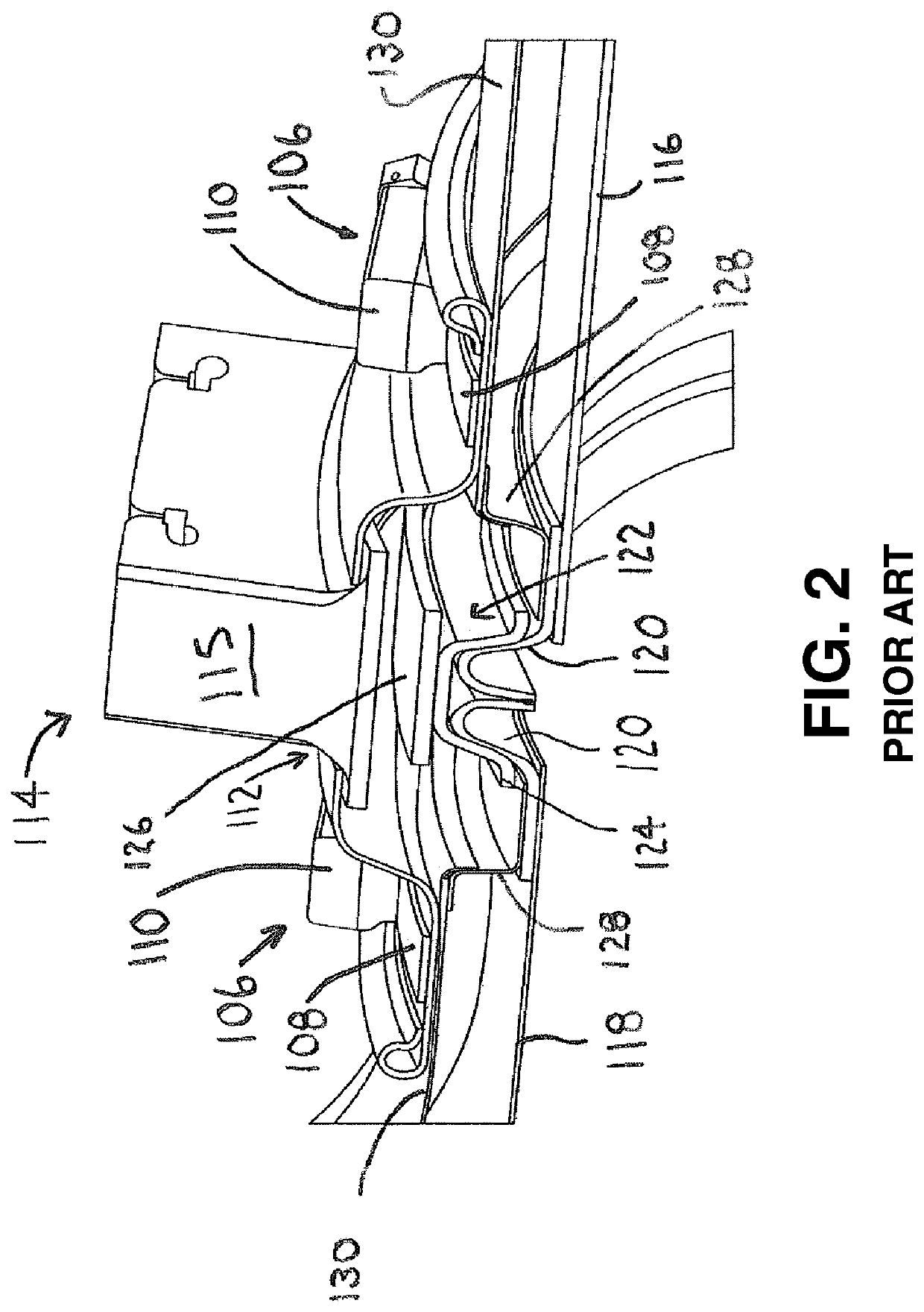
[0014]When the metallic duct develops a crack, the hot air leaks from duct interior to the insulation blanket. The insulation blanket changes the characteristics of the hot air leakage 1) by absorbing the thermal energy and reducing the air temperature; 2) by reducing the effective pressure due to pressure drop; and 3) by reducing the volume by diffusing the air in the annulus between metal duct and insulation shell throughout the length of the duct.
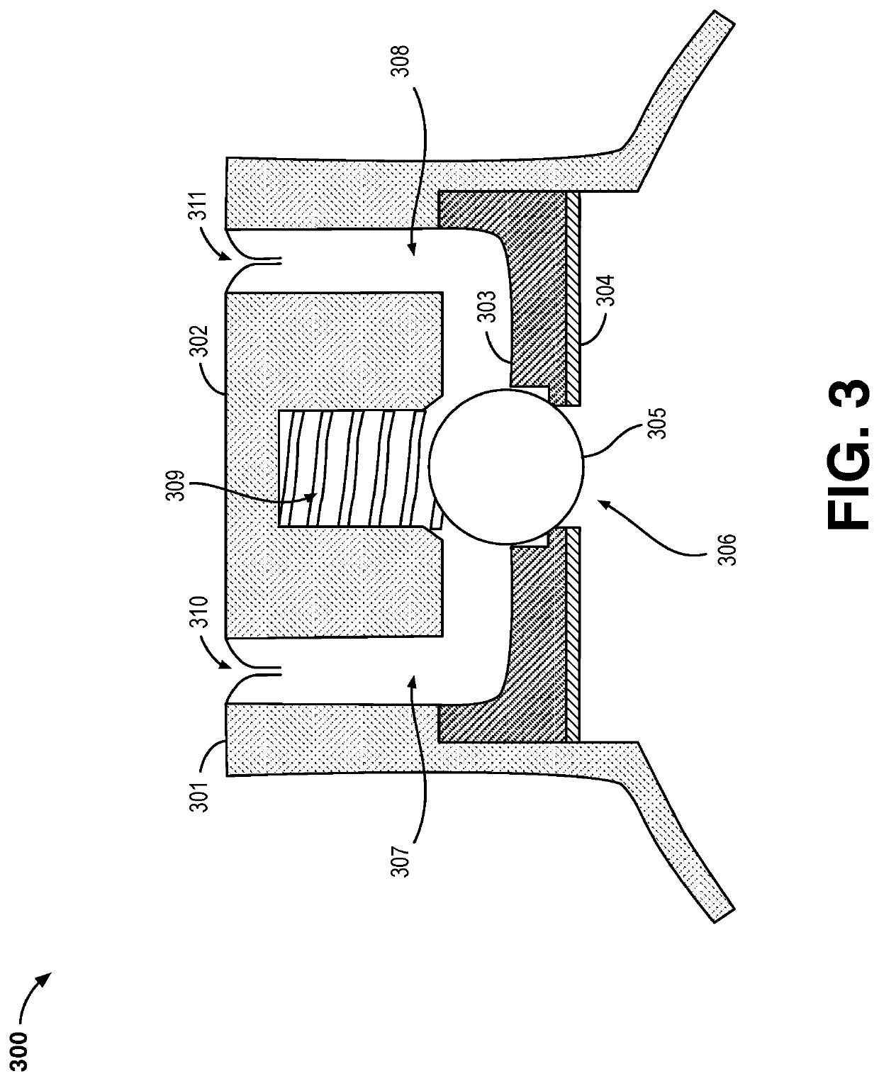
[0015]Leak detection devices described herein may include manifold assemblies formed from two or more different materials. In a preferred embodiment, an elastomeric manifold body may include one or more metal plates adhered thereto or integrated therein, which serve to reinforce the elastomer and to maintain the shape of the manifold body under high temperatures, pressures and external loads. The combination of metal and elastomer provides structural integrity, resists deformation due to thermal expansion and other environmental forces, and provides a consistent and robust seal due to the flexibility and compressibility of the elastomer.
[0020]In some embodiments of the invention, the at least one rigid aperture control plate is a bottom aperture control plate. In a preferred embodiment, the manifold assembly also includes a top aperture control plate. In this embodiment, the top aperture control plate includes an elongated cutout, and is disposed substantially proximate to a top end of the manifold block so as to substantially align the elongated cutout with the one or more gas passages. The top aperture control plate is also adapted to further maintain the substantial circularity of the inlet aperture.
[0021]The manifold assembly may also include a set screw disposed within the manifold block adjacent to the flow control valve. The set screw is operably adjustable to extend and retract toward and from a spring element of the flow control valve, thereby increasing and decreasing respectively the amount of force applied by the flow control valve against the inlet aperture.
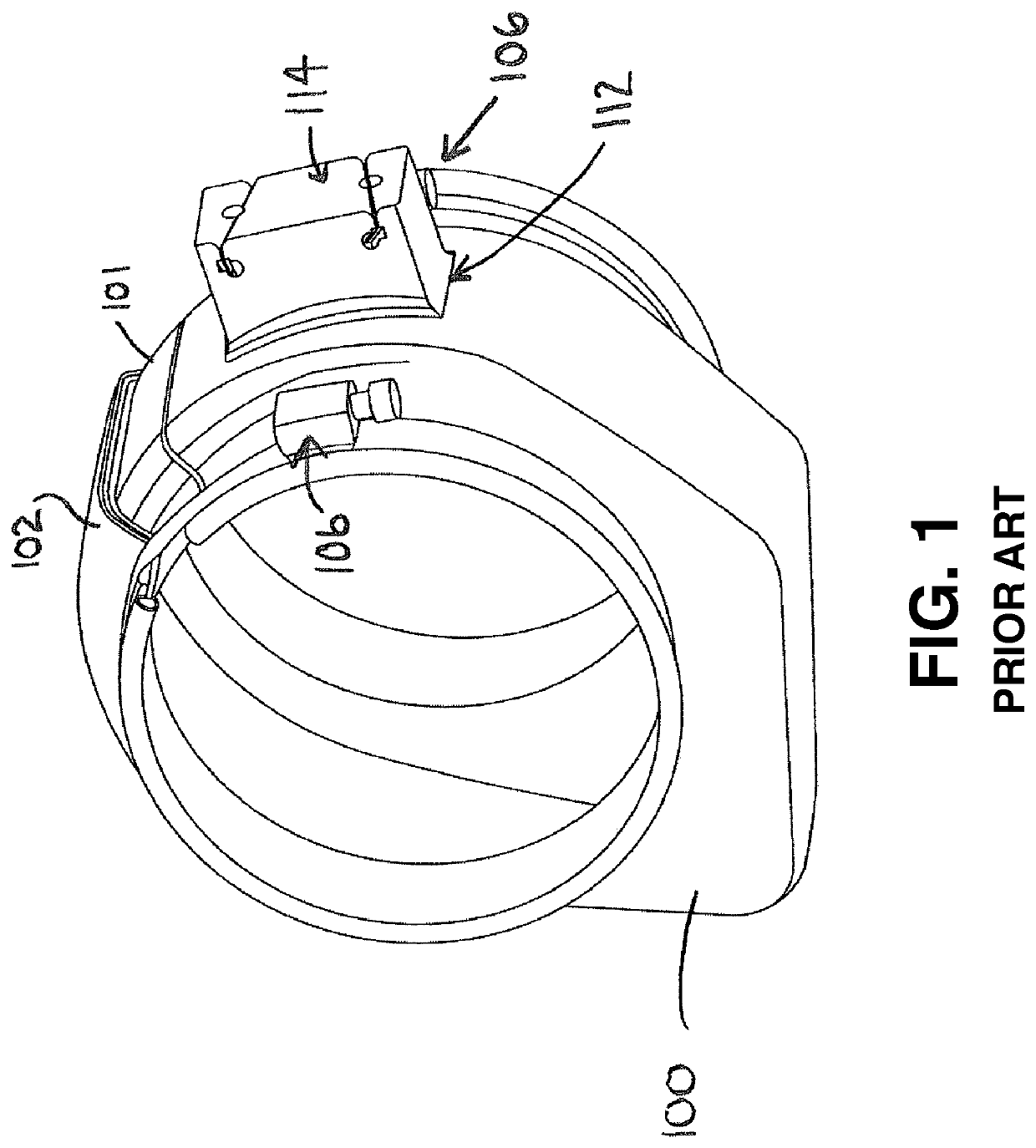
[0025]According to a second aspect of the present invention, there is provided a joint cover apparatus, for a ducting system for transporting high temperature pressurized gases, for covering a joint between abutting duct sections, wherein the ducting system is provided with a leak detection system using one or more temperature-responsive sensor wires. The joint cover apparatus includes a split joint cover body, operably configured to be expanded. The split joint cover body is positionable circumferentially around a joint between abutting duct sections and has an aperture therethrough, to permit the passage of gases emanating from the joint to a location external to the split joint cover body. The joint cover apparatus also includes at least one clamping mechanism, operably configured to releasably engage the split joint cover body, to cause the split joint cover body to be contracted around the joint. The joint cover apparatus also includes an elastomeric manifold block having a substantially circular inlet aperture and one or more gas passages having upper ends and fluidly coupled to the inlet aperture.

Problems solved by technology

If sufficient air pressure exists at low volume, air flow velocity cannot be sustained once the volume is quickly depleted.
When the metallic duct develops a crack, the hot air leaks from duct interior to the insulation blanket.

Method used


Image

  • Joint cover with improved manifold block for duct leak detection system
  • Joint cover with improved manifold block for duct leak detection system
  • Joint cover with improved manifold block for duct leak detection system

Examples


Embodiment Construction

[0047]There will now be described by way of examples, several specific modes of the invention as contemplated by the inventors. In the following description numerous specific details are set forth in order to provide a thorough understanding. It will be apparent however, to one skilled in the art, that the present invention may be practiced without limitation to these specific details. In other instances, well known methods and structures have not been described in detail so as not to unnecessarily obscure the description.

[0048]Leak detection devices of the present application may be integrated within a joint cover for a ducting system. When two separate ducts abut, an annular “cuff” may be secured around the joint. The two separate ducts may be secured together in various ways, such as with clamps or flanges. In some instances, the joint cover or cuff may protrude radially outward, forming an annular chamber that surrounds the joint. A joint cover may have integrated therein a mani...


PUM


Abstract

A manifold assembly configured for integration with a joint cover apparatus in a ducting system to detect leaking gas comprises an elastomeric manifold block having a substantially circular inlet aperture and one or more gas passages fluidly coupled to the inlet aperture. The assembly includes a flow control valve configured to maintain a closed state in which a component of the flow control valve sealingly engages with the inlet aperture to preclude gas at the inlet aperture from flowing into the one or more gas passages until said gas reaches a pressure corresponding to a pressure threshold. The assembly also includes at least one aperture control plate disposed substantially proximate to a lower end of the manifold block and including a substantially circular opening. The aperture control plate is adapted to maintain the substantial circularity of the inlet aperture, so as to ensure a substantially fluid-tight seal.

Description

FIELD OF THE INVENTION[0001]The present invention relates to the field of aerospace, and, in particular, to modern aircraft which utilize the flow of hot compressed bleed air from the engines for various on-board functions.BACKGROUND OF THE INVENTION[0002]The present invention relates to the use of ducting systems in aircraft structures. Amongst the prior art, it is well known in the art to use high temperature bleed air from the engines for various on-board purposes in a modern aircraft. Typically, a stream of hot air bled from the engines is used to provide an anti-icing function on the leading edge of the wings and empennage of the aircraft and is also used by the air conditioning units to supply fresh air to the passenger cabin. The bleed air must therefore be transported from the engines to various other areas of the aircraft, and this is typically accomplished utilizing insulated metallic ducts ranging in diameter from 1.00″ to 6.50″ and ranging in length from at least 6″. The...

Claims


Application Information

Patent Timeline
Patent Type & Authority Patents(United States)
IPC IPC(8): F01D9/02F02C6/08B64D13/02F16L59/18F01D17/20F01D17/02F01D25/00F16L23/16F16K15/04F02C7/00B64D13/06
CPCF01D25/00F01D17/20F16L23/16F02C7/00F01D17/02F02C6/08F01D9/023F16K15/044F16L59/184B64D13/02B64D2013/0607F05D2300/10F05D2260/606
Inventor POSSERT, ERIC M.OWDEH, MUHANNADALI, KARIM
Owner SENIOR IP GMBH
Why Eureka
Eureka Blog
Learn More