
Method for producing multilayer submicron particles by laser pyrolysis

a technology of laser pyrolysis and submicron particles, which is applied in the direction of chemical vapor deposition coating, inorganic chemistry, nanotechnology, etc., can solve the problems of limited types and possible number of uses of these particles, and achieve the effect of preventing any oxidation of the silicon cor

Active Publication Date: 2020-04-07
NANOMAKERS
View PDF18 Cites 1 Cited by
  • Summary
  • Abstract
  • Description
  • Claims
  • Application Information

AI Technical Summary

Benefits of technology

The invention provides a process to produce submicron particles of non-oxidized silicon with a protective carbon layer preventing oxidation. This process improves the homogeneity of distribution and thickness of the layer of second element on each particle core, especially when no agent for oxidizing the first chemical element is used. The technical effect is the ability to produce high-quality silicon particles with excellent oxidation protection.

Problems solved by technology

However, such a process has several drawbacks:the types and possible number of uses of these particles are limited and it could be sought to produce particles enabling novel uses, andthe homogeneity of distribution and thickness of the carbon layer on each silicon particle core is open to improvement.

Method used


Image

  • Method for producing multilayer submicron particles by laser pyrolysis
  • Method for producing multilayer submicron particles by laser pyrolysis
  • Method for producing multilayer submicron particles by laser pyrolysis

Examples


third embodiment

[0153]Particles according to the first example were produced with the first, second and third embodiment of the device 9 alone or in combination.

[0154]The size of the particles 10 obtained corresponds to a core diameter comprised between 10 and 500 nm (with a standard deviation between 2 and 60 nm), and a layer thickness 16 between 1 and 5 nm. The particles are not necessarily perfectly spherical. By core diameter is meant the distance linking the two most distant points of the core (for example the length in the case of a rod-shaped core).

first embodiment

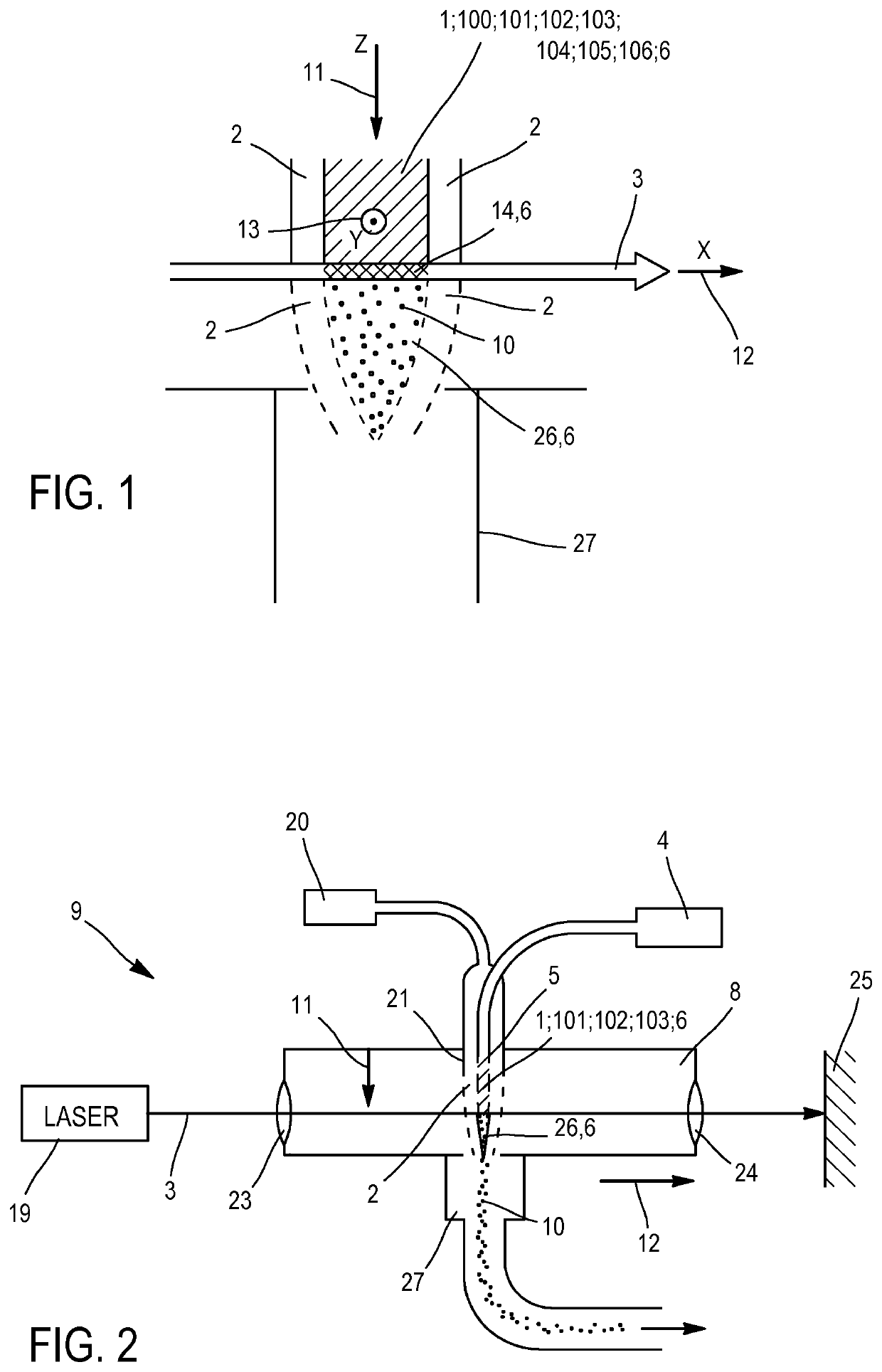
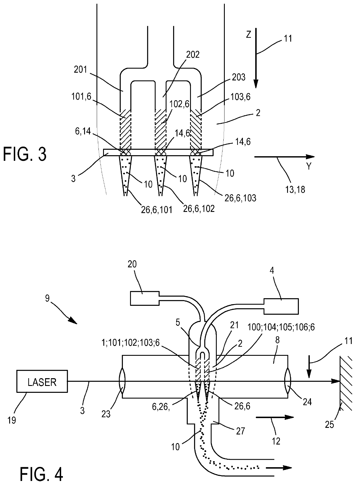
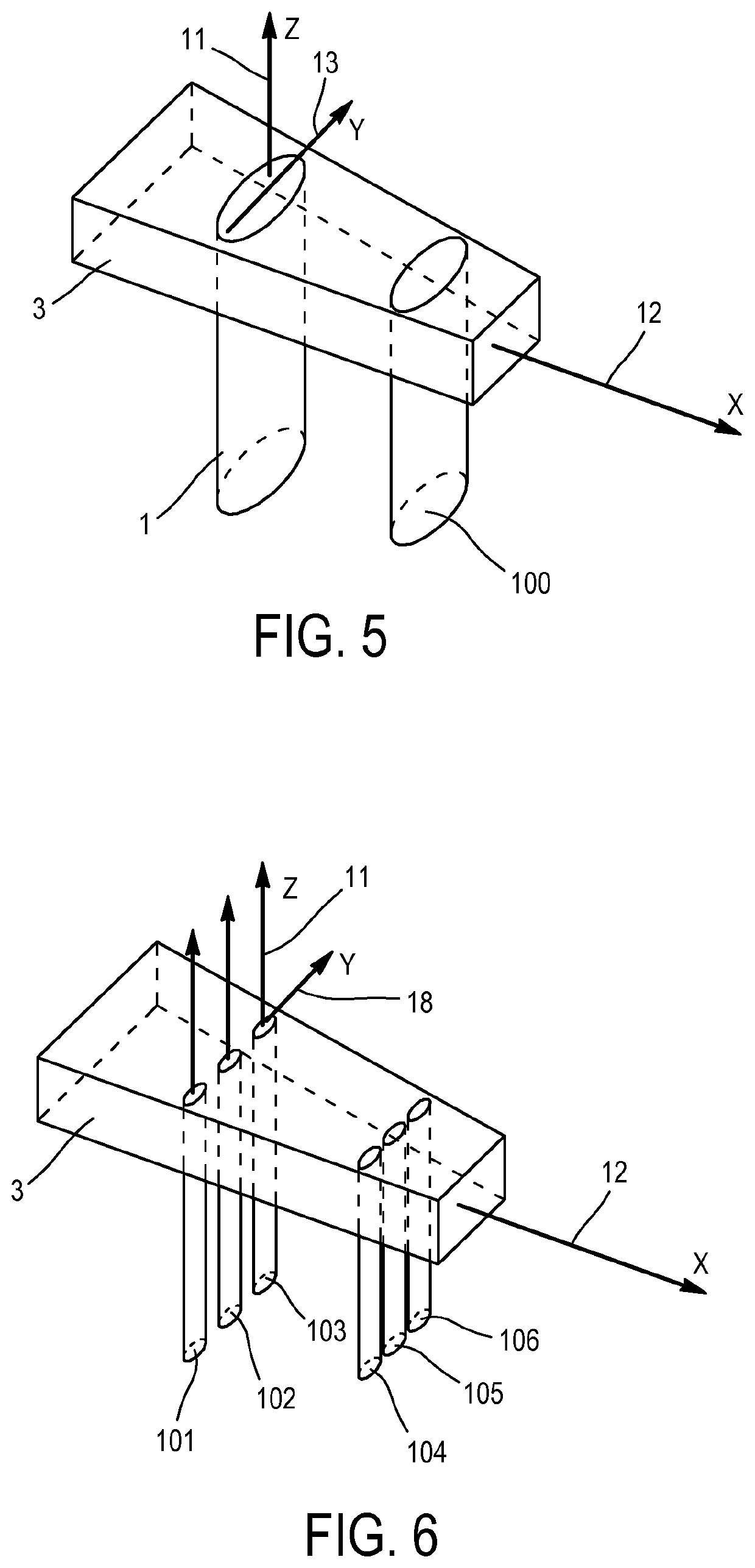
[0155]Using the device according to the invention, for which the second chemical element is introduced into the chamber 8 with the first chemical element in each reaction flow 1, 100, 101, 102, 103, 104, 105, 106, it is observed that the layer 16 is not perfectly uniform, as illustrated in FIG. 9.

[0156]This may be due to the fact that according to the invention each reaction flow is devoid of agent oxidizing the first chemical element. The fact of not using any oxidizing agent is counter-intuitive, particularly in the case of a layer 16 of carbon, as oxidizing agents are known to dehydrogenate molecules such as C2H4, C6H6 etc. and thus to assist the formation of solid carbon.

[0157]Better results are observed from the second or third embodiment alone than from the first embodiment alone.

[0158]The homogeneity of the layer 16 can be markedly improved by using the second and / or third embodiment of the device according to the invention, wherein the second chemical element is introduced i...


PUM

PropertyMeasurementUnit
thicknessaaaaaaaaaa
thicknessaaaaaaaaaa
frequencyaaaaaaaaaa

Abstract

Disclosed is a method for producing particles, including the steps: introducing, into a reaction chamber, at least one reaction flow including a first chemical element and propagating in a direction of flow; projecting a radiation beam through the reaction chamber, intersecting each reaction stream in one interaction area per reaction flow, to form, in each reaction flow, particle cores including the first chemical element; and introducing, into the reaction chamber, a second chemical element interacting with each reaction flow to cover the particle cores with a layer including the second chemical element. Each reaction flow is preferably free of any agent oxidizing the first chemical element. Preferably a ratio of one atom of the second element is introduced per unit of time for at least two atoms of the first element introduced per unit of time. The second element is preferably introduced in at least one confined flow.

Description

TECHNOLOGICAL FIELD[0001]The present invention relates to a process for producing multilayer particles (typically a core layer covered by an upper layer), typically by laser pyrolysis. It also relates to an associated device.[0002]Such a process for example allows a user to produce submicron particles of silicon each covered with a layer of carbon.PRIOR ART[0003]A process is known for producing particles of silicon oxide covered with a layer of carbon by laser pyrolysis as described in the document U.S. Pat. No. 6,387,531.[0004]However, such a process has several drawbacks:[0005]the types and possible number of uses of these particles are limited and it could be sought to produce particles enabling novel uses, and[0006]the homogeneity of distribution and thickness of the carbon layer on each silicon particle core is open to improvement.[0007]The purpose of the invention is to remedy at least one or more of the drawbacks listed above.DISCLOSURE OF THE INVENTION[0008]This objective is...

Claims


Application Information

Patent Timeline
Patent Type & Authority Patents(United States)
IPC IPC(8): B01J19/08B82Y30/00C01B33/029C01B32/05C01B33/02C23C16/44C01B33/027
CPCB01J19/08C01B32/05C23C16/4417C01B33/029C01B33/02C01B33/027B82Y30/00C01P2004/62C01P2004/84C01P2004/64B01J2219/0869Y10T428/2993B01J2219/0879C01P2004/80C23C16/442
Inventor TENEGAL, FRANCOIS
Owner NANOMAKERS
Learn More