Spectral imaging method and system

a spectral imaging and method technology, applied in the field of imaging techniques, can solve the problems of low light efficiency, low spatial resolution of images, and complex systems implementing such techniques

Active Publication Date: 2020-03-31
TECH INNOVATION MOMENTUM FUND ISRAEL
View PDF28 Cites 4 Cited by
  • Summary
  • Abstract
  • Description
  • Claims
  • Application Information

AI Technical Summary

Benefits of technology

[0009]Thus, the present invention provides for acquiring a complete hyperspectral cube of arbitrary scene with full spatial and spectral resolutions, while having a simple construction of standard imaging system, additionally equipped with a tunable dispersive element (spectral filter) with broad spectral transmission profiles that allows acquiring within each frame a weighted sum of wavelengths. The hyperspectral imaging system of the invention could be integrated within both color (Bayer) and monochrome image sensors. The clear aperture Fabry-Perot etalon may also be used for standard color imaging, thus enabling a dual-purpose imaging system (standard color+hyperspectral). The system has improved noise performance, since each frame is acquired with reduced noise content.
[0011]The present invention takes advantage of the hyperspectral imaging technique described in U.S. patent application No. 62 / 075,972, assigned to the assignee of the present application, and incorporated herein by reference. This technique is based on applying angular coding on an input light field while creating an optical image thereof, thus providing angular multiplexing of hyperspectral image data (hyperspectral cube). This technique is effectively operable for objects of a size that can be imaged on at least N pixels of the pixel array to allow reconstruction of N spectral bands.
[0013]The tunable etalon is configured for tunability over a relatively wide spectral range, and also preferably with sufficient Free Spectral Range (FSR). Furthermore, in order to enable generation of accurate color images, the etalon is preferably configured with low finesse (namely sufficiently wide spectral transmission peak). This, on the one hand, provides for creating images with accurate (e.g. faithful) colors, and, on the other hand, allows sufficient light to pass to the sensor (pixel matrix).
[0014]The etalon typically includes a pair of substantially parallel, generally reflective surfaces, spaced from one another by a gap (optical distance). Generally, the transmission function T of such etalon is a function of wavelength λ, transmission of the two surfaces, and the value of gap between these surfaces. For the etalon formed by given reflective surfaces (i.e. given transmission(s) thereof), the etalon's transmission is a function of wavelength and gap, T(λ, gap). Thus, by controllably varying the gap between the reflective surface to provide a sequence of n different gap values during image acquisitions of n frames (n exposures), respectively, different n transmission functions of the etalon are applied to the input light field which differently affect detection of light components of n wavelengths λ1, . . . λN by the pixel matrix of the detector. This allows reconstruction of the spectrum of the object by processing the image data of n frames.

Problems solved by technology

However, these techniques require prior knowledge of the scene being imaged, and also typically suffer from low light efficiency, and systems implementing such techniques are rather complex.
This method allows fast hyperspectral cube acquisition, but the resultant image suffers from low spatial resolution; also the required setup could not be integrated in common cameras.

Method used


Image

  • Spectral imaging method and system
  • Spectral imaging method and system
  • Spectral imaging method and system

Examples


Embodiment Construction

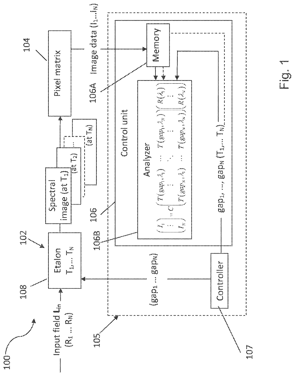
[0030]Reference is made to FIG. 1 illustrating, by way of a block diagram, a hyperspectral imaging system 100 of the invention. The imaging system 100 includes an optical unit 102 for locating in front of (upstream of) an imaging plane IP defined by a pixel matrix unit 104 of a detector, and a control system 105. The control system 105 includes a control unit 106 configured for data communication with a readout circuit of the pixel matrix 104 for receiving image data therefrom and processing the received data. The control unit 106 may be integral with the pixel matrix unit 104, e.g. may be a software module of the readout circuit of the pixel matrix unit 104.

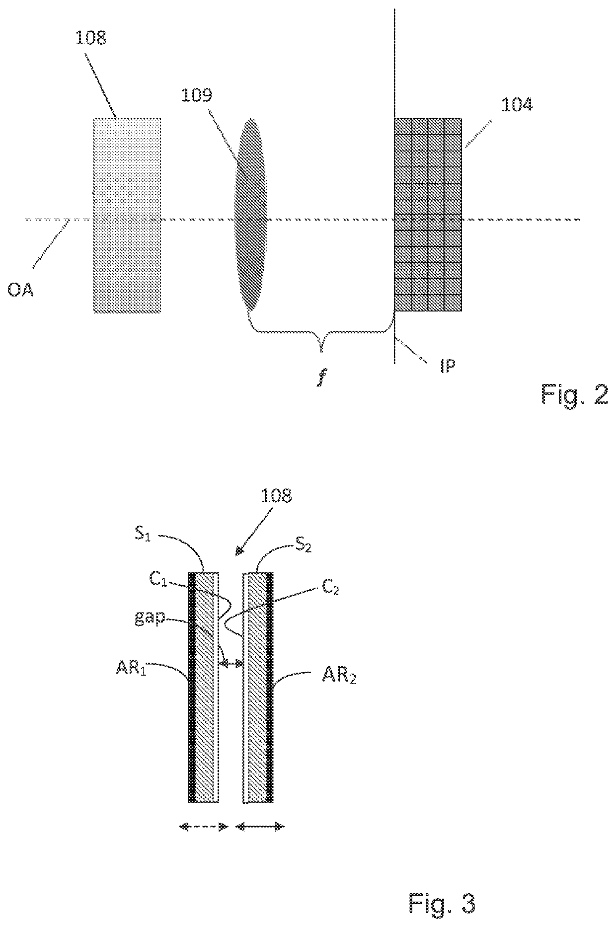
[0031]The optical unit 102 includes a tunable dispersive unit / element being a wide spectral filter 108. For example, a clear aperture Fabry-Perot etalon with wide transmission peak can be used.

[0032]The control unit 106 includes inter alia data input and output utilities (not shown), a memory module 106A, an analyzer module 106B...


PUM


Abstract

A hyperspectral imaging system and method are presented for use in reconstruction of spectral data of an object. The system comprises: a pixel matrix of a detector; a tunable dispersive unit in front of the pixel matrix; and a control system. The control system comprises: a controller for tuning the dispersive unit during n image acquisition sessions to provide n different partially overlapping spectral transmission profiles of the dispersive unit; and a control unit which is in data communication with the detector and is configured and operable for processing n image data pieces generated by the pixel matrix in said n image acquisition sessions respectively, each being indicative of a spectral image detected by the pixel matrix and corresponding to the different spectral transmission profile of the dispersive unit, and determining the reconstructed spectral data of the object.

Description

TECHNOLOGICAL FIELD AND BACKGROUND[0001]The present invention is in the field of imaging techniques, and relates to a method and system for spectral imaging.[0002]Spectral imaging is aimed at providing at least some spectral information about an object at every location in an image plane. Various spectral imaging techniques have been developed, including multispectral imaging, hyperspectral imaging, full spectral imaging, imaging spectroscopy or chemical imaging. Spectral images are often represented as an image cube, a type of data cube.[0003]Multispectral (MS) and hyperspectral (HS) cubes could be acquired in many ways. Some systems (utilizing whiskbroom, pushbroom and tunable filters for realizing HS imagers), rely on multiple acquisitions of 1D or 2D subsets of the 3D HS cube followed by simple reconstruction. Some other systems include polychromatic sensors that trade-off resolution with spectral information (similar to the Bayer CFA) and require spatio-spectral reconstruction ...

Claims


Application Information

Patent Timeline
Patent Type & Authority Patents(United States)
IPC IPC(8): G01J3/28G16H40/63G16H30/20G01J3/02G01J3/26G01J3/50G01J3/12
CPCG01J3/0264G01J3/502G01J3/2823G01J3/26G16H30/20G01J3/2803G16H40/63G01J2003/2813G01J2003/2826G01J2003/1247G01B9/02G01J3/45G16Z99/00
Inventor RAZ, ARIELMENDLOVIC, DAVID
Owner TECH INNOVATION MOMENTUM FUND ISRAEL
Why Eureka
Try Eureka