
Stacker crane with an improved sliding mechanism

a technology of sliding mechanism and stout crane, which is applied in the direction of lifting devices, storage devices, instruments, etc., can solve the problems of transporting material falling or even the stacker overturning, the risks described above occur in even greater measures, and the fastening between the movable structure and the wheel is not screwed, so as to improve the storing/retrieving dynamism, reduce wear, and improve the dynamism of storing/retrieving

Active Publication Date: 2020-03-24
INPECO
View PDF5 Cites 1 Cited by
  • Summary
  • Abstract
  • Description
  • Claims
  • Application Information

AI Technical Summary

Benefits of technology

The solution provides increased stability and accuracy in the movement of biological material test tubes, preventing material falling or crane overturning, while enhancing throughput and reducing maintenance complexity.

Problems solved by technology

Problems appear with a sliding movement of this type since a lack of accuracy and / or instability can occur in certain cases.
This can be due for example to the presence of frictions during the sliding movement, various imbalances caused by the progressive wearing out of the wheels over time, impurities depositing on the wheels or still again to the possibility of an unscrewing at the fastenings between the movable structure and wheels.
The latter drawback can naturally result in the transported material falling or even the stacker overturning.
The risks described above occur in even greater measure the higher the stacker is, or if it is designed to transport particularly heavy materials or materials sensitive to overturning.
Such a solution therefore allows the rack to move easily during the loading and unloading operations from the locations, but involves a significant mechanical stress when the load is cantilevered moved by means of the aforesaid telescopic extension.
The need for increasingly more storage space therefore requires the use of increasingly voluminous storages and the necessary application of suitable movement systems, for example of the type corresponding to the aforesaid stacker cranes, thus also adding the problems disclosed above connected with movement to the complexities of the storing systems themselves.

Method used


Image

  • Stacker crane with an improved sliding mechanism
  • Stacker crane with an improved sliding mechanism
  • Stacker crane with an improved sliding mechanism

Examples


Embodiment Construction

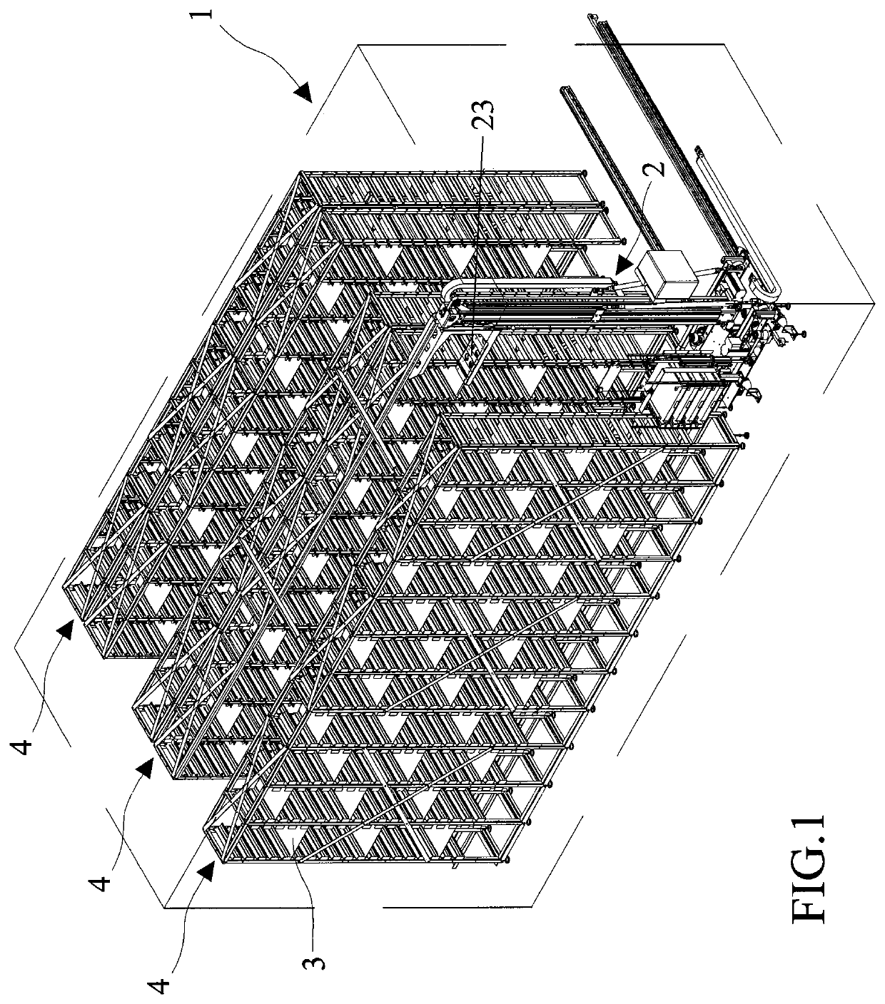
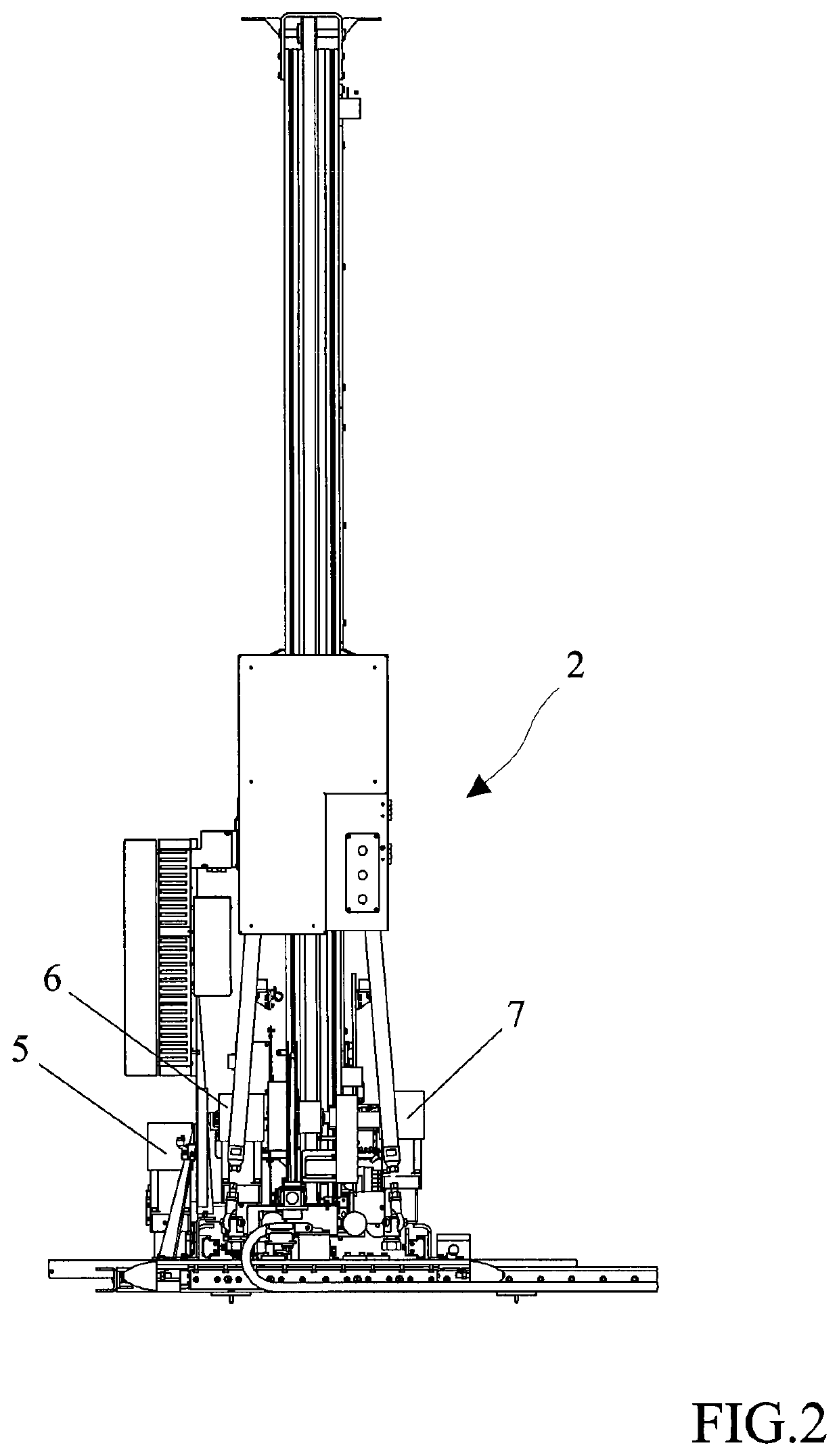
[0033]FIG. 1 shows a storage 1 for storing material, in particular containers of biological material test tubes, comprising a stacker crane 2, or hereinafter stacker, designed to transport containers of the aforesaid material and to insert and pick them in / from locations 3 of a plurality of shelves 4 of the storage 1. The stacker crane 2 is able to conveniently move the containers of biological material test tubes in the three Cartesian directions x, y and z, so as to reach the locations 3. In particular, the stacker 2 is capable of first being positioned at the feet of the suitable shelf 4, then rising along the vertical so as to reach the suitable height, in front of the specific location 3 to be reached.

[0034]In the embodiment herein disclosed, with particular reference to FIG. 1, the storage 1 comprises a plurality of shelves 4 facing each other, which define suitable lanes for the movement of stacker 2 between two shelves 4 facing each other. Moreover, the shelves 4 are arrange...


PUM

PropertyMeasurementUnit
translational movementaaaaaaaaaa
sliding frictionaaaaaaaaaa
frictionsaaaaaaaaaa

Abstract

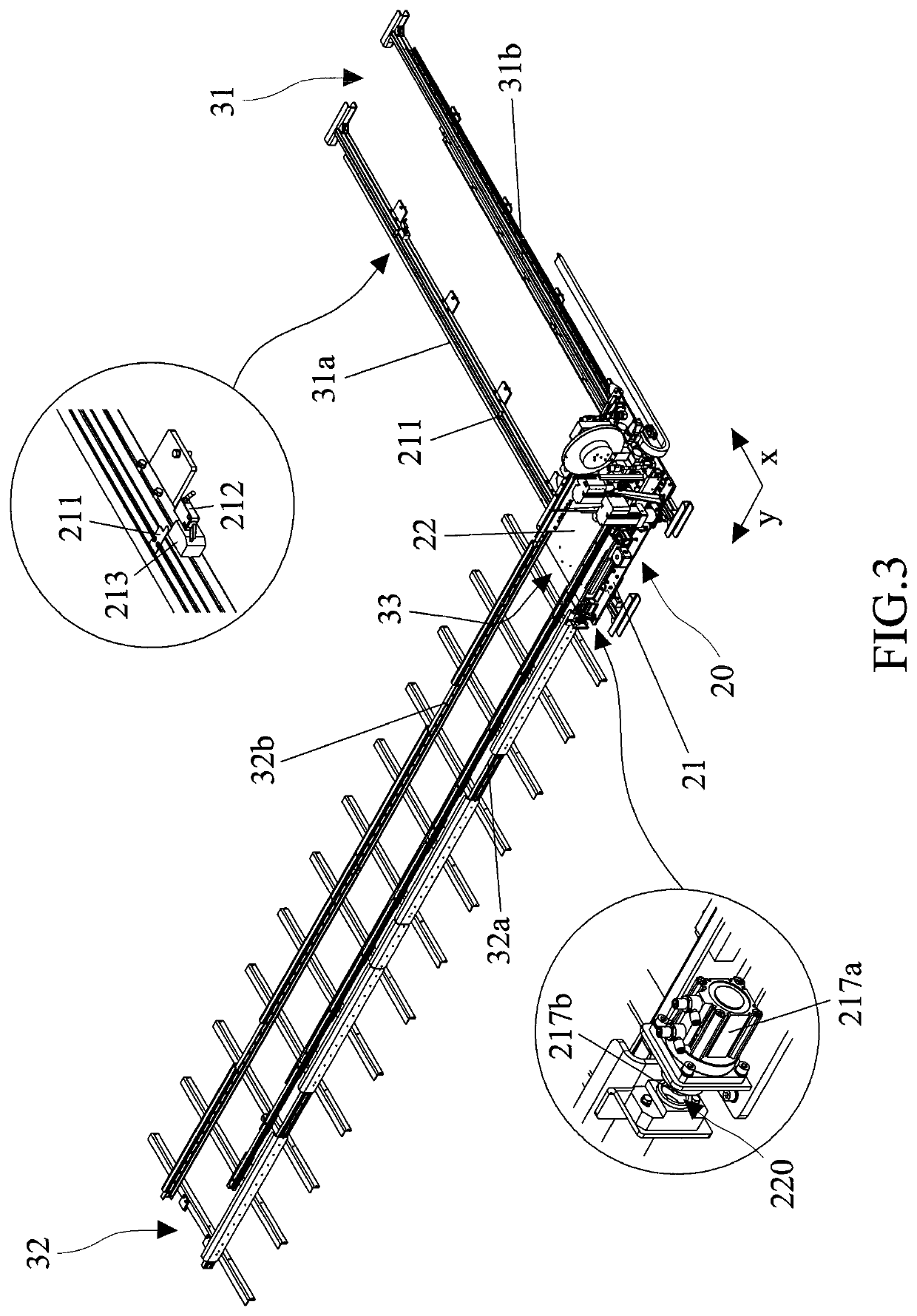
The present invention relates to a stacker crane (2) for transporting, inserting and picking containers of biological material test tubes in / from locations (3) of a plurality of shelves (4) of a warehouse (1) for storing containers of biological material test tubes. The stacker crane (2) is able to move the containers of biological material test tubes in the three Cartesian directions x, y and z, so as to reach the locations (3), wherein the stacker (2) comprises a first carriage (21) and a second carriage (22) able to slide independently of, and to be released from, the first carriage (21) in direction y.

Description

BACKGROUND OF THE INVENTION[0001]The present invention relates to a stacker crane with an improved sliding mechanism and to a storage for storing containers of biological material test tubes provided with said stacker crane.[0002]Stacker cranes, also more simply referred to as stackers, are now employed in the most various fields of industrial automation for the automated transport of different types of materials inside large warehouses, as well as for inserting and / or picking material from specific locations of shelves, often significantly high off the ground.[0003]The sliding movement of the movable structure of the stacker in known solutions is promoted, in particular in movements along direction y, by the presence of wheels, which adequately accompany the movement of the movable structure along the tracks.[0004]Problems appear with a sliding movement of this type since a lack of accuracy and / or instability can occur in certain cases. This can be due for example to the presence o...

Claims


Application Information

Patent Timeline
Patent Type & Authority Patents(United States)
IPC IPC(8): B65G1/04G01N35/04B66F9/07B66F9/14
CPCB66F9/072B66F9/141G01N35/04B66F9/07B65G1/0414G01N2035/0425
Inventor PEDRAZZINI, GIANANDREA
Owner INPECO
Learn More