
Non-telecentric emissive micro-pixel array light modulators and methods of fabrication thereof

a technology of emissive micro-pixel array and light modulator, which is applied in the direction of optics, instruments, electrical equipment, etc., can solve the problems of increasing the cost and volumetric aspects of the overall display system, increasing the system complexity, bulk and cost, and undesirable ghost distortions in the directionally modulated 3d imag

Active Publication Date: 2020-03-03
OSTENDO TECH INC
View PDF276 Cites 4 Cited by
  • Summary
  • Abstract
  • Description
  • Claims
  • Application Information

AI Technical Summary

Benefits of technology

The patent text describes a new type of display technology called SSL imagers that use non-telecentric light emission. These imagers have a unique capability to emit light in a way that is not dictated by the external light source, making them more versatile and useful for a variety of applications. The technical effect of this patent is to extend the design and manufacturing methods of SSL imagers to include the capability of non-telecentric light emission for the numerous possible applications that stand to benefit from such capability.

Problems solved by technology

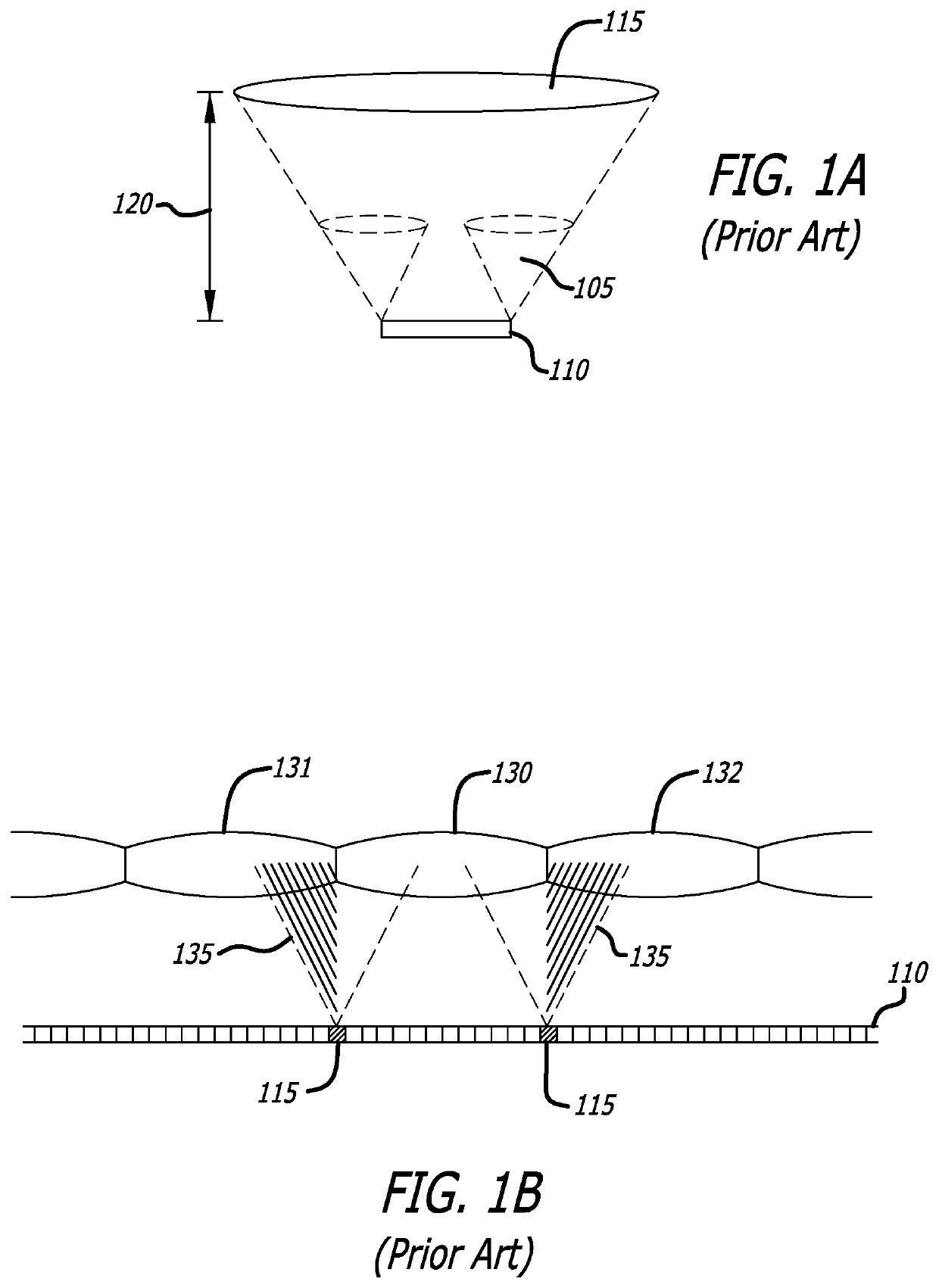
In the case of reflective and transmissive SLMs, telecentric light modulation is dictated by the design limitations of their external light source.
This effect, which is often referred to as “cross-talk”, causes undesirable “ghost” distortions in the directionally modulated 3D image.
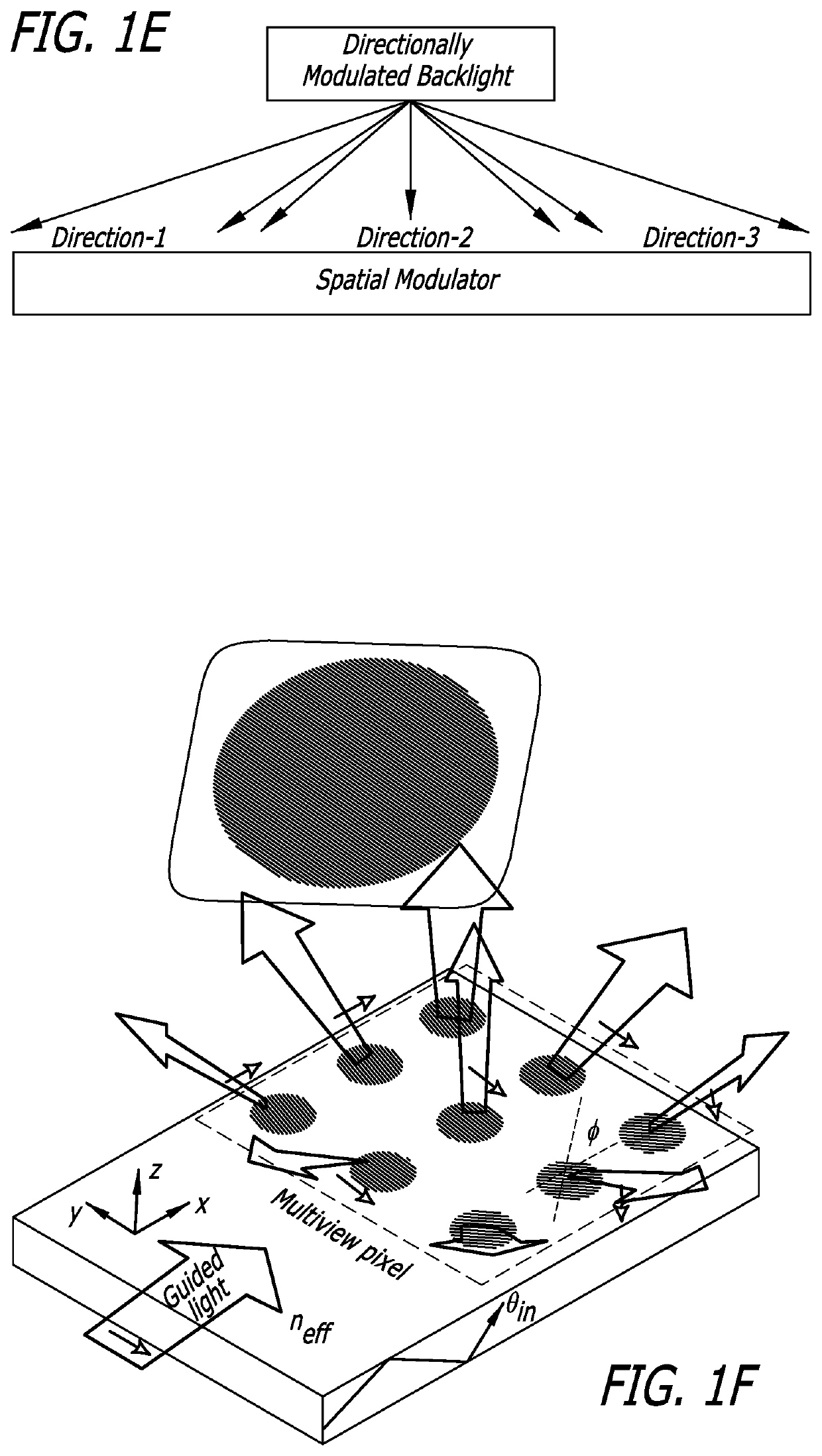
In addition to being slow, bulky and optically lossy, the prior art directional backlight units typically need to have narrow spectral bandwidth, high collimation and individual controllability for being combined with a directionally selective filter for 3D display purposes.
Achieving narrow spectral bandwidth and high collimation requires device level innovations and optical light conditioning, increasing the cost and the volumetric aspects of the overall display system.
Achieving individual controllability requires additional circuitry and multiple light sources, increasing the system complexity, bulk and cost.

Method used


Image

  • Non-telecentric emissive micro-pixel array light modulators and methods of fabrication thereof
  • Non-telecentric emissive micro-pixel array light modulators and methods of fabrication thereof
  • Non-telecentric emissive micro-pixel array light modulators and methods of fabrication thereof

Examples


Embodiment Construction

[0047]References in the following detailed description of the present invention to “one embodiment” or “an embodiment” means that a particular feature, structure, or characteristic described in connection with the embodiment is included in at least one embodiment of the invention. The appearances of the phrase “in one embodiment” in various places in this detailed description are not necessarily all referring to the same embodiment.

[0048]In the description to follow, references are made to the word groups, such as in a directional modulation groups of micro pixels and similar references. When a non-telecentric emissive micro-pixel array light modulator in accordance with the present invention is to display a light field, reference to a group of pixels or to the corresponding micro optical elements is a reference to the pixels or micro optical elements associated with a single hogel. When the present invention is to display one or more two dimensional scenes at the same time, referen...


PUM

PropertyMeasurementUnit
angle of divergenceaaaaaaaaaa
surface areaaaaaaaaaaa

Abstract

Emissive micro-pixel spatial light modulators with non-telecentric emission are introduced. The individual light emission from each multi-color micro-scale emissive pixel is directionally modulated in a unique direction to enable application-specific non-telecentric emission pattern from the micro-pixel array of the emissive spatial light modulator. Design methods for directionally modulating the light emission of the individual micro-pixels using micro-pixel level optics are described. Monolithic wafer level optics methods for fabricating the micro-pixel level optics are also described. An emissive multi-color micro-pixel spatial light modulator with non-telecentric emission is used to exemplify the methods and possible applications of the present invention: ultra-compact image projector, minimal cross-talk 3D light field display, multi-view 2D display, and directionally modulated waveguide optics for see-through near-eye displays.

Description

CROSS-REFERENCE TO RELATED APPLICATIONS[0001]This application claims the benefit of U.S. Provisional Patent Application No. 62 / 271,637 filed Dec. 28, 2015.BACKGROUND OF THE INVENTION[0002]1. Field of the Invention[0003]Non-telecentric emission spatial light modulators, emissive micro-pixel displays, ultra-compact image projectors, directional light modulators, multi-view 2D displays, 3D displays, near-eye displays, head-up displays.[0004]2. Prior Art[0005]Spatial light modulators (SLMs) are a class of optoelectronic devices having a planar array of micro-scale pixels that are typically used as an image source in display systems. Such light modulators typically fall in one of three distinctive categories: reflective, transmissive or emissive. Examples of reflective SLMs include micro mirror array devices and liquid crystal on silicon (LCoS) devices. Examples of transmissive SLMs include high temperature poly-silicon liquid crystal (HTPS) devices. Examples of emissive SLMs include emi...

Claims


Application Information

Patent Timeline
Patent Type & Authority Patents(United States)
IPC IPC(8): G02B26/08H04N13/398G02B27/00G02B26/00H04N13/30G02F1/29G02B30/10
CPCG02B27/0018H04N13/398G02B30/00H04N13/30G02B27/0075G02B30/50G02B30/10G02B6/003G02B6/0046G02B6/0058
Inventor EL-GHOROURY, HUSSEIN S.PITCHUMANI, MAHESHALPASLAN, ZAHIR Y.CHUANG, CHIH-LIMCNEILL, DALE A.
Owner OSTENDO TECH INC
Learn More