
Systems and methods for suppressing oscillator-induced spurs in frequency synthesizers

a frequency synthesizer and oscillator technology, applied in the direction of electrical equipment, automatic control, pulse, etc., can solve the problems of affecting the performance and accuracy of the pll, the output signal of the vco can sometimes be unstable, etc., and achieve the effect of reducing the frequency of the oscillator

Active Publication Date: 2020-02-18
MARVELL ASIA PTE LTD
View PDF4 Cites 3 Cited by
  • Summary
  • Abstract
  • Description
  • Claims
  • Application Information

AI Technical Summary

Benefits of technology

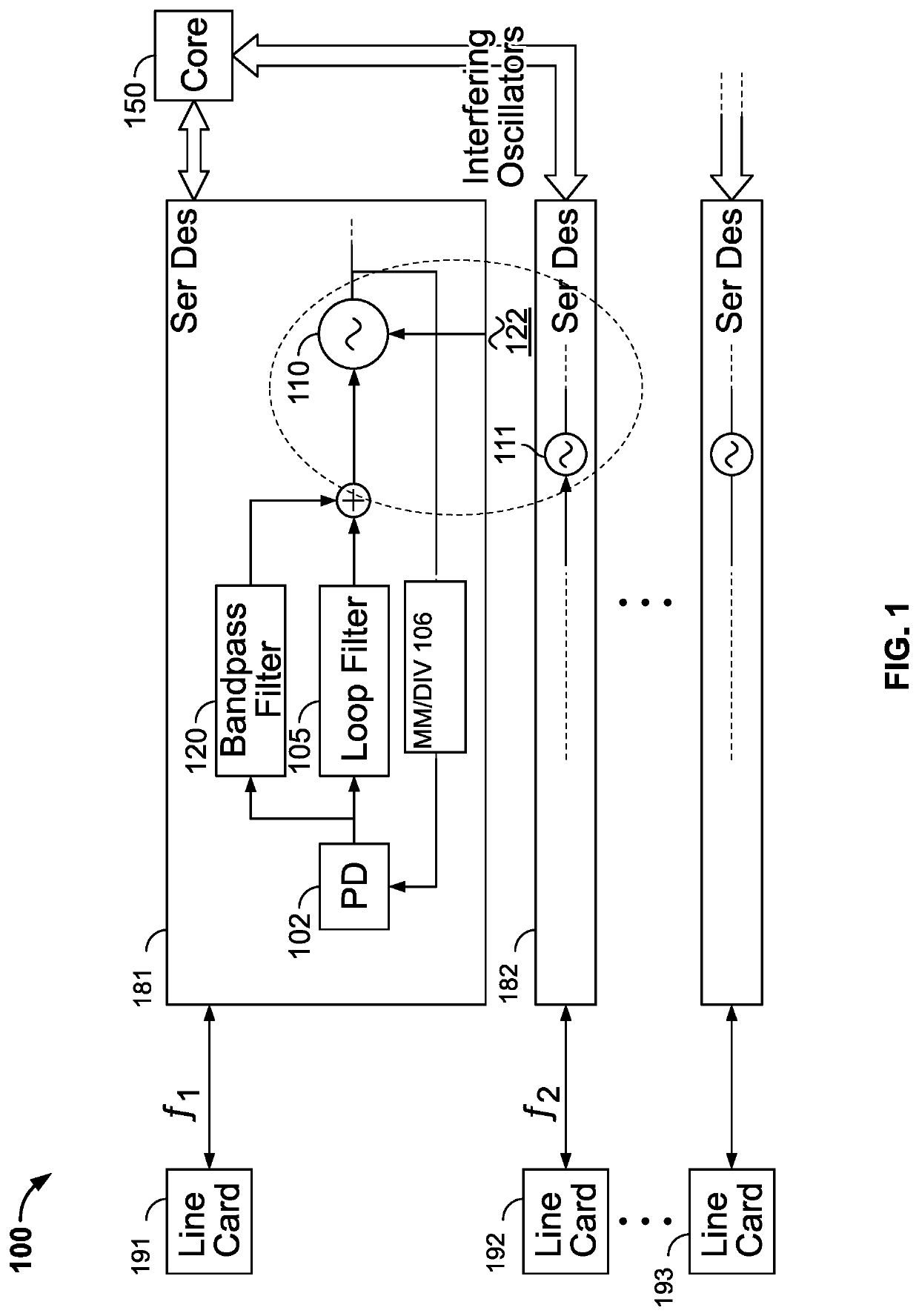
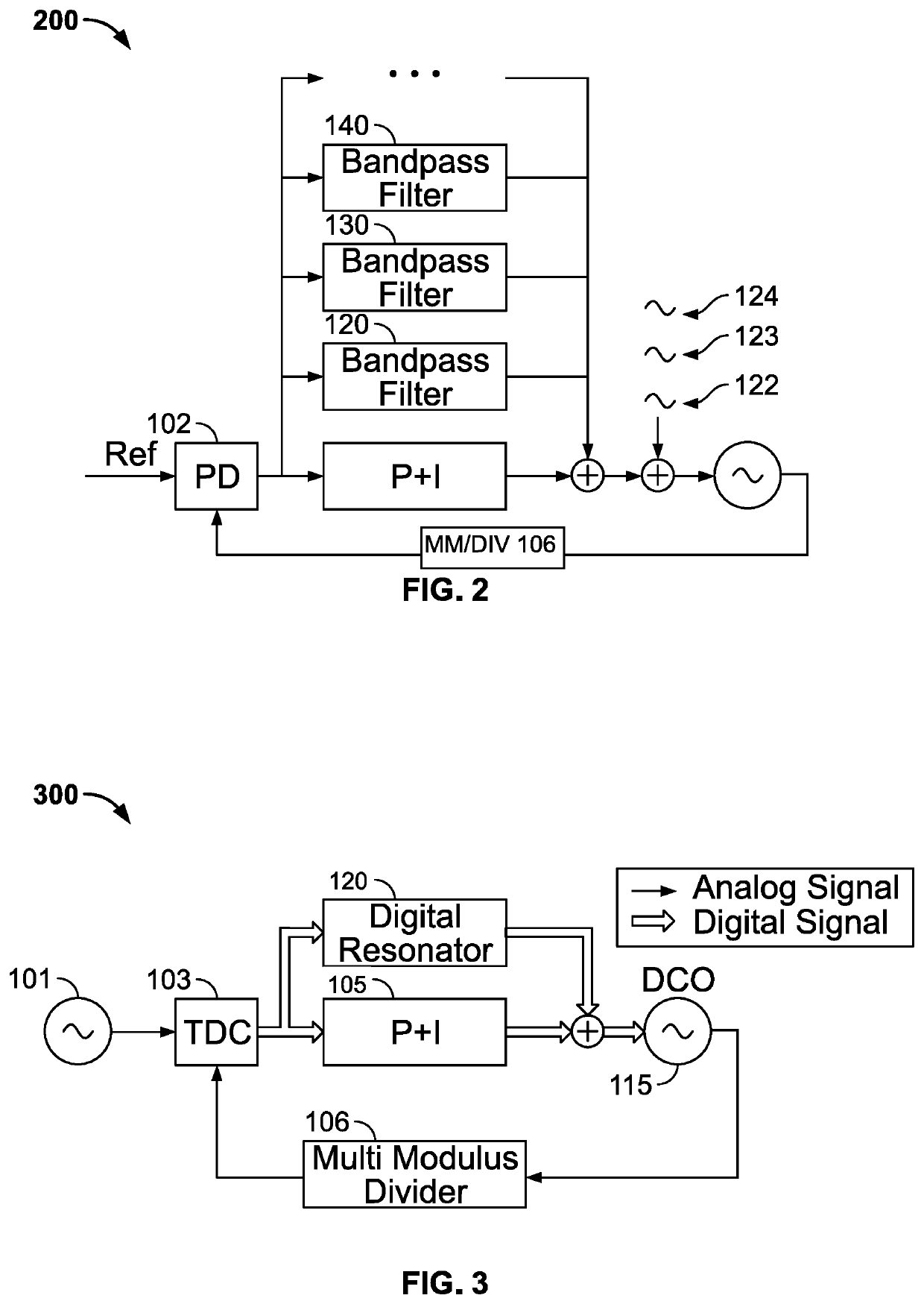
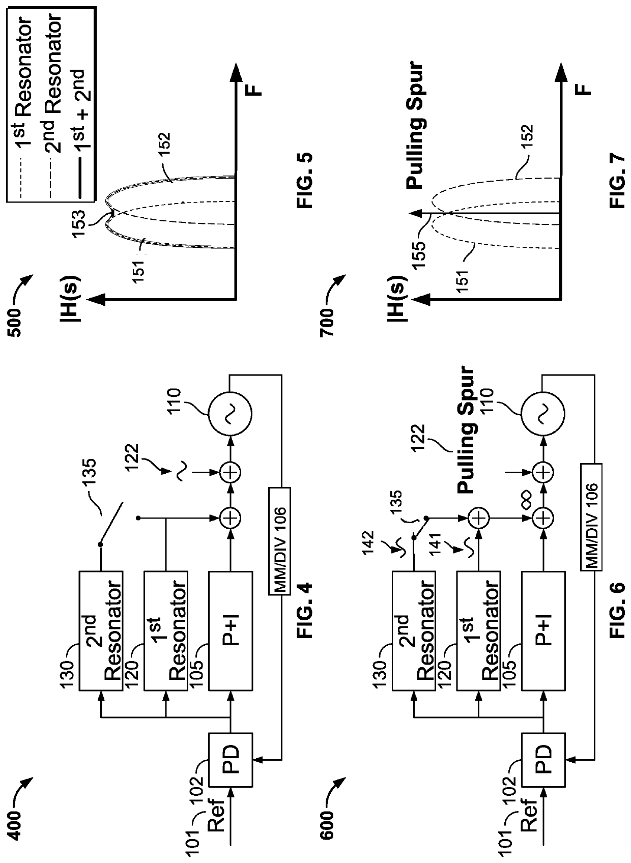
The patent describes a way to decrease interference between clock signals in an electronic device. A first clock signal is generated, and a second clock signal is also outputted from another oscillator on the device. The first clock signal has additional signals caused by the second oscillator, which is filtered out using a bandpass filter. The filtered signal is combined with a control signal for the first oscillator, which helps mitigate the interference and produce a higher quality clock signal.

Problems solved by technology

However, some oscillators, such as a voltage-controlled oscillator (VCO) employed to generate the output signal, are generally sensitive to various factors such as temperature, noise in power supplies, electro-magnetic interference, etc., and thus the output signal of the VCO can sometimes be unstable, whether because of such environmental factors or because of cross talk and / or interference as a result of interaction with signals generated by other oscillators on the same electronic device.
The oscillator-induced spurs in the PLL negatively impact the performance and accuracy of the PLL.

Method used


Image

  • Systems and methods for suppressing oscillator-induced spurs in frequency synthesizers
  • Systems and methods for suppressing oscillator-induced spurs in frequency synthesizers
  • Systems and methods for suppressing oscillator-induced spurs in frequency synthesizers

Examples


Embodiment Construction

[0039]This disclosure describes methods and systems for adaptive suppression for oscillator-induced spurs in frequency synthesizers. For example, when a circuit includes one or more oscillators, the clock signal generated from one of the oscillators is sometimes affected by interference between the oscillators, causing a spurious aberration in the clock signal. For another example, for a network device that includes a number of serializers and deserializers (e.g., see 181, 182 in FIG. 1), each of which is configured to communicate with different devices and each has its own oscillator to generate a clock signal, interference between oscillators on the same circuit cause spurs in the clock signals generated from the oscillators. Specifically, such signal spurs are likely to be added to the oscillator output signals, e.g., see 122 in FIG. 1. Embodiments described herein provide a bandpass filter added to the device with a pass band configured to be centered around the frequency of the...


PUM


Abstract

Embodiments described herein provide an electronic device, which includes a first oscillator configured to output a first clock signal, and a second oscillator that is co-located with the first oscillator on the electronic device. The electronic device further includes a first bandpass filter configured to filter a first input signal derived from the first clock signal received through a negative feedback loop, and to output a first signal component corresponding to the first signal spur. The electronic device further includes a signal reconstruction circuit configured to receive the first signal component and to combine the first signal component into a control signal for the first oscillator, and to feed the control signal combined with the first signal component to the first oscillator to mitigate the first signal spur exhibited in the first clock signal.

Description

CROSS-REFERENCE TO RELATED APPLICATION[0001]This disclosure claims the benefit under 35 U.S.C. § 119(e) of U.S. Provisional Patent Application No. 62 / 421,725, filed Nov. 14, 2016, which is hereby incorporated by reference herein in its entirety.FIELD OF USE[0002]This disclosure relates to noise reduction in a frequency synthesizers, and specifically, to systems and methods for suppressing oscillator-induced spurs in frequency synthesizers.BACKGROUND OF THE DISCLOSURE[0003]The background description provided herein is for the purpose of generally presenting the context of the disclosure. Work of the inventors hereof, to the extent the work is described in this background section, as well as aspects of the description that does not otherwise qualify as prior art at the time of filing, are neither expressly nor impliedly admitted to be prior art against the present disclosure.[0004]Frequency synthesis is widely used in computing devices, such as wireless communication devices, medical ...

Claims


Application Information

Patent Timeline
Patent Type & Authority Patents(United States)
IPC IPC(8): H03L7/10H03L7/107H03L7/14H03L7/16
CPCH03L7/16H03L7/1075H03L7/143H03L7/093H03L7/099H03L7/18
Inventor VERCESI, LUCADE BERNARDINIS, FERNANDO
Owner MARVELL ASIA PTE LTD
Learn More