
Communication system controlled motorized in-line disconnect switch with improved lock out system

a technology of lockout system and communication system, which is applied in the direction of air-break switch details, hot sticks switches, emergency actuators, etc., can solve problems such as safety issues, and achieve the effect of safe and secure lockou

Active Publication Date: 2020-02-18
CLEAVELANDPRICE ENTERPRISES
View PDF8 Cites 2 Cited by
  • Summary
  • Abstract
  • Description
  • Claims
  • Application Information

AI Technical Summary

Benefits of technology

The present invention provides a lock out system for a communication system controlled in-line motorized high voltage disconnect switch that can safely and securely lock the switch blade of the switch from operational movement. The lock out system can be operated wirelessly remote control for safe use of the switch. The lock out system includes a separate dedicated locking motor powered by the switch battery. The lock out system can be used in emergency situations to prevent the switch from closing while workers are in contact with the line. The lock out system includes a safety cover that must be flipped open to access the hot stick and prevent motor operation or manual operation from reclosing the switch. The manual operation safety cover can be closed after the switch has been opened manually. The invention provides a secure and safe way to lock the switch and prevent safety issues.

Problems solved by technology

In the event the switch battery is not functioning or other unforeseen issues cause a failure of the switch or the lock out to operate, the utility will then need to send a bucket truck crew to the switch to manually operate the switch and lock out lever with a hot stick.
If the open switch motor is no longer energized then the switch's housing can now be removed to allow resolution of the malfunction of the switch without concern of the switch motor starting resulting in a safety issue.

Method used


Image

  • Communication system controlled motorized in-line disconnect switch with improved lock out system
  • Communication system controlled motorized in-line disconnect switch with improved lock out system
  • Communication system controlled motorized in-line disconnect switch with improved lock out system

Examples


Embodiment Construction

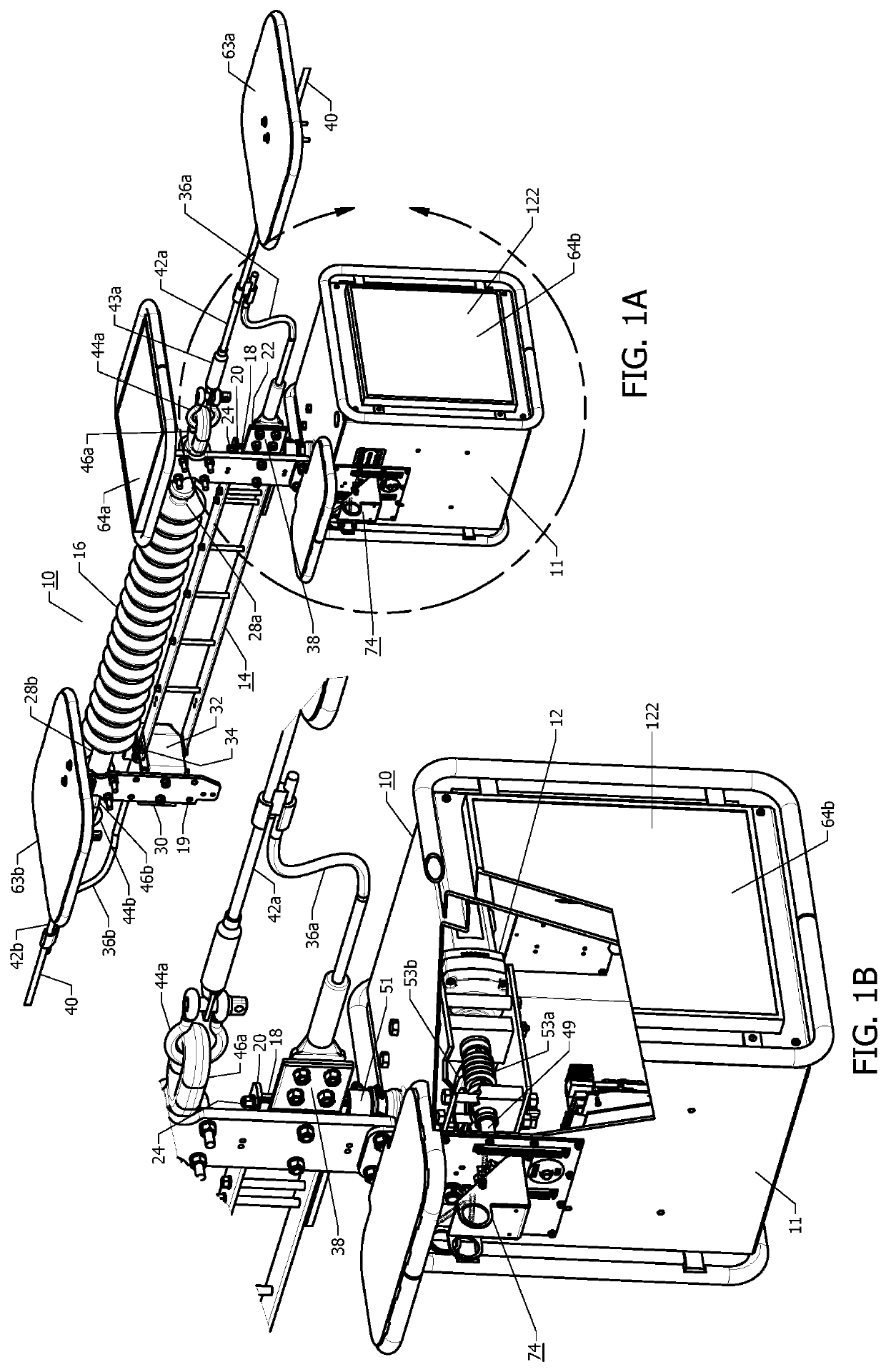
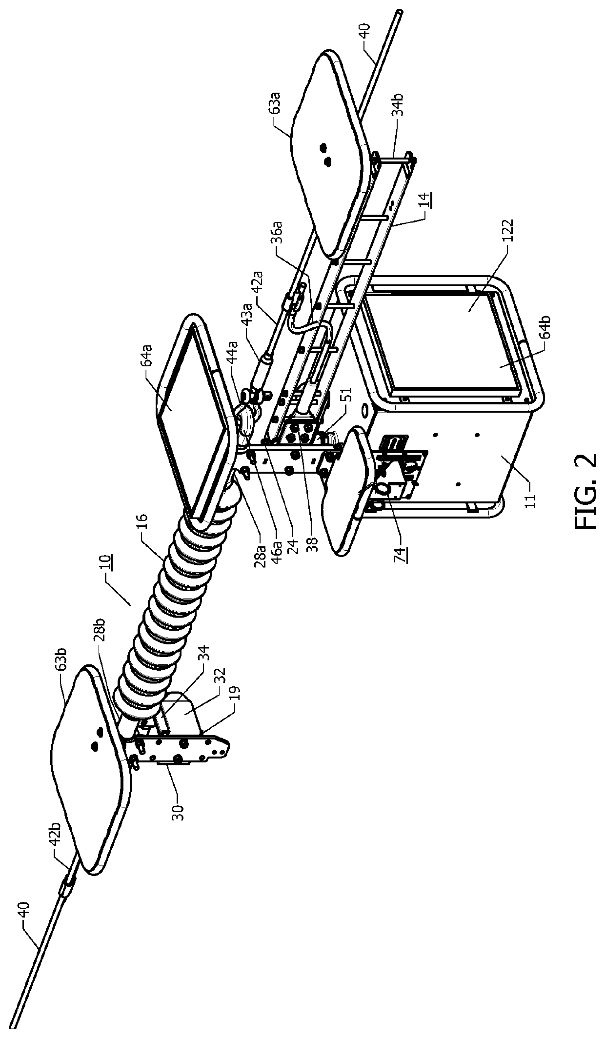
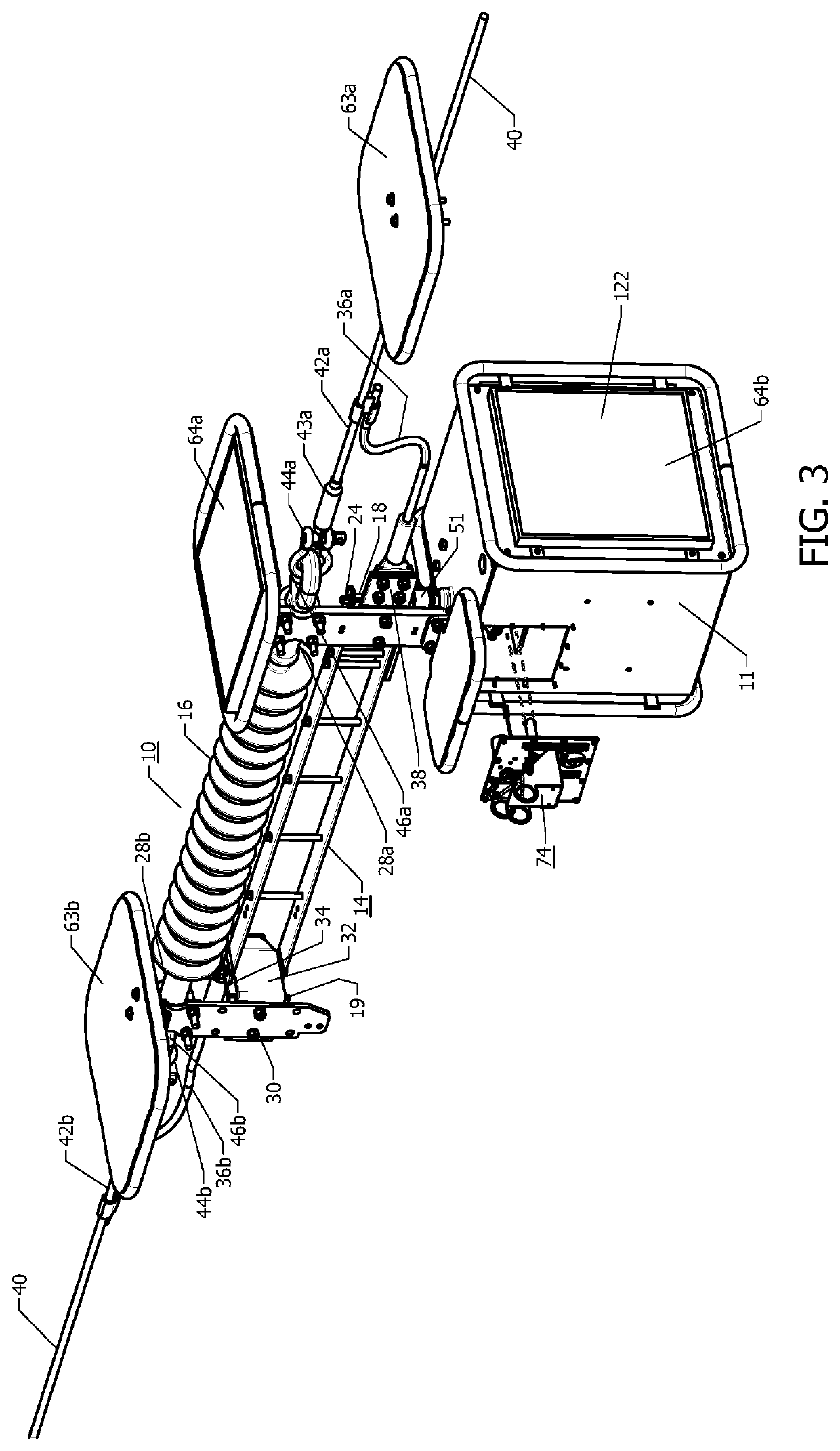
[0026]With reference to FIGS. 1A, 1B, 2 and 3 a communication system controlled motorized in-line high voltage air break disconnect switch 10 of the present invention is shown. In this embodiment a side break high voltage disconnect switch is depicted. Of course this invention is applicable to other types of communication system controlled motorized in-line high voltage air break disconnect switches including vertical break switches as referenced in said U.S. Pat. No. 9,881,755 B1 and U.S. Pat. No. 9,966,207 B1 and double break type switches referenced in said U.S. patent application Ser. No. 16 / 271,795. FIG. 1B depicts the switch 10 with the housing 11 enclosing a switch blade drive motor 12. The housing 11 is partially broken away to reveal the switch blade drive motor 12 and certain other components described subsequently. Reference should also be made to FIGS. 8 and 9 in this regard. The communication system controlled motorized in-line side air break switch 10 of the present in...


PUM


Abstract

A communication system controlled motorized in-line high voltage air break disconnect switch with a lock out system including a communication device remote controlled lock out. Also a mechanical lock out is provided if a battery that powers the remote controlled lock out is not functioning or other unforeseen problems cause a failure of the switch or the remote controlled lock out to operate. The remote controlled lock out when operative can prevent the switch from operating the motor when the remote controlled lock out is actuated. The motorized switch typically includes the motor having a worm drive shaft carrying a hookstick eye ring. The remote controlled lock out includes a locking gear mounted on the drive shaft. A lockout lever having a locking tooth is provided that engages or disengages the locking gear when appropriately actuated by the remote control to lock or unlock the switch blade drive motor.

Description

CROSS-REFERENCE TO RELATED APPLICATION[0001]This application claims the benefit of U.S. Provisional Application No. 62 / 722,852 filed Aug. 25, 2018, which is incorporated herein by reference in its entirety.BACKGROUND OF THE INVENTION[0002]The present invention relates generally to an air break disconnect switch for high voltage electrical applications and, more particularly, to a communication system controlled motorized in-line high voltage air break disconnect switch that mounts in-line with the transmission line conductor without the need of a group operated switch with associated ground supported mounting structure. Such a communication system controlled motorized in-line high voltage disconnect switch hangs from and is supported by its associated transmission line. In particular, the present invention is directed to a novel system for locking out such a switch for safety reasons.[0003]One example of a non-communication system controlled non-motorized in-line high voltage discon...

Claims


Application Information

Patent Timeline
Patent Type & Authority Patents(United States)
IPC IPC(8): H01H31/08H01H31/00H01H31/02H01H31/34
CPCH01H31/026H01H31/08H01H31/006H01H31/34H01H2221/068
Inventor KOWALIK, PETER M.ANDREYO, JOSEPH K.
Owner CLEAVELANDPRICE ENTERPRISES
Learn More