Fuel supply device

a technology of a fuel supply device and a chamfering portion, which is applied in the direction of liquid fuel feeders, machines/engines, transportation and packaging, etc., can solve the problems of difficult to increase the curvature radii of the chamfering portion, cracks may form at the corners, etc., to relieve stress concentration, relieve stress concentration, and relieve the effect of stress concentration

Active Publication Date: 2020-01-28
AISAN IND CO LTD
View PDF33 Cites 6 Cited by
  • Summary
  • Abstract
  • Description
  • Claims
  • Application Information

AI Technical Summary

Benefits of technology

[0007]According to one aspect of the present disclosure, a fuel supply device may comprise a cover-side unit configured to close an opening formed on an upper wall of a fuel tank of a vehicle, a pump-side unit having a fuel pump that may be disposed within the fuel tank, and a coupling mechanism configured to couple the pump-side unit to the cover-side unit in a vertically slidable manner. The coupling mechanism may include a fixed-side rail member (or members) having a rail portion (or portions) that is provided as part of the cover-side unit and extends in a vertical direction, and a movable-side rail member (or members) that is provided as part of the pump-side unit and has a rail groove (or grooves) configured in a channel groove shape that can slidably engage with the rail portion of the fixed-side rail member. A recess (or recesses) with a semi-circular cross section is formed at a corner (or corners) of the rail groove (or grooves) of the movable-side rail member (or members) for relieving stress concentrations at the corner (or corners).
[0008]With this structural configuration, it is possible to relieve the concentration of the stress at the corner (or corners) of the rail groove of the movable-side rail member whenever the vehicle utilizing the fuel supply device is involved in a collision. The recess is formed at the corner (or corners) of the rail groove of the movable-side rail member. Therefore, being formed in such a manner, said recess may prevent the rail groove from interfering with the rail portion of the fixed-side rail member unlike the case in the prior art described above where curvature radiuses of chamfered portions at corners are increased. Accordingly, it is possible to relieve stress concentrations at the corner (or corners) of the rail groove of the movable-side rail member while avoiding the interference of said corner of the rail groove with the rail portion of the fixed-side rail member.
[0009]According to another aspect of the present disclosure, the rail groove (or grooves) of the movable-side rail member (or members) includes an inner end face (or faces) and two groove lateral faces. The recess (or recesses) may be formed at the inner end face (or faces) at the corner (corners) of the rail groove (grooves) and recessed in a direction laterally opposite the rail portion of the fixed-side rail member. This structural configuration of the recess (or recesses) can reduce and / or prevent stress concentrations at the corner (or corners) of the rail groove (or grooves) while maintaining the strength provided by both walls defined by the both groove lateral faces of the rail groove (or grooves).
[0010]According to another aspect of the present disclosure, a metallic slider (or sliders) capable of improving the sliding property between members, by decreasing friction when sliding against one another, is interposed between the rail portion (or portions) of the fixed-side rail member (or members) and the rail groove (or grooves) of the movable-side rail member (or members). Therefore, it is possible to reduce and / or prevent generation of abnormal noise caused by direct sliding contact of the both rail members.
[0011]According to another aspect of the present disclosure, a stopper (or stoppers) is formed at a lower end (or ends) of the rail groove (or grooves) of the movable-side rail member (or members), wherein the stopper (or stoppers) is configured to prevent excessive upward movement of the movable-side rail member (or members) with respect to the rail portion (or portions) of the fixed-side rail member (or members). With such a stopper being present, it is possible to reduce the likelihood of and / or prevent a possible malfunction that may occur as a result of the excessive upward movement of the pump-side unit if the fuel tank contracts in response to the variation of the internal pressure within the tank. In addition, with the structural configuration as described, it is possible to reduce and / or prevent the excessive contraction of the fuel tank in the upward and downward direction.
[0012]According to another aspect of the present disclosure, the stopper (or stoppers) may be formed with an inclined surface configured to prevent said stopper (or stoppers) from being caught by an edge of the opening formed in the upper wall of the tank. Therefore, when the pump-side unit is inserted into the fuel tank, the inclined surface may prevent the stopper from being caught on any such edge of the opening, and allow easier and smoother entry of the pump-side unit into the tank.

Problems solved by technology

As a result, damage such as a crack may form at the corners.
Therefore, it is difficult to increase the curvature radii of the chamfered portions 213.

Method used


Image

  • Fuel supply device
  • Fuel supply device
  • Fuel supply device

Examples


Embodiment Construction

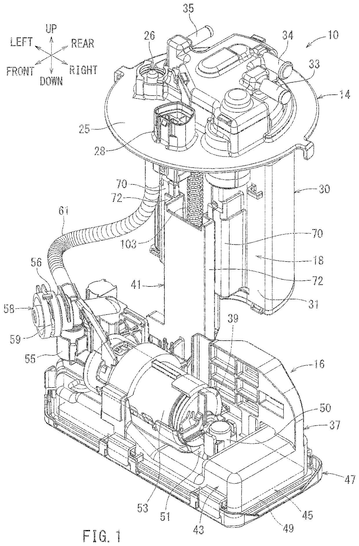
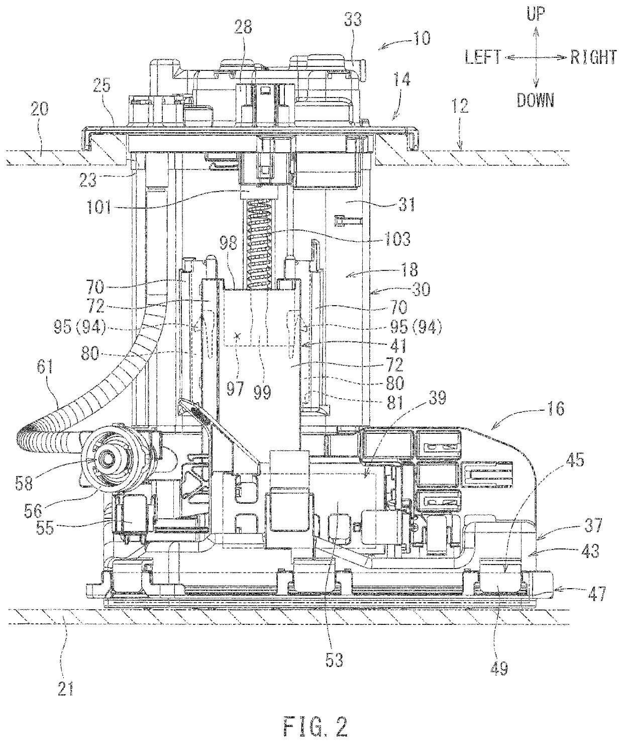
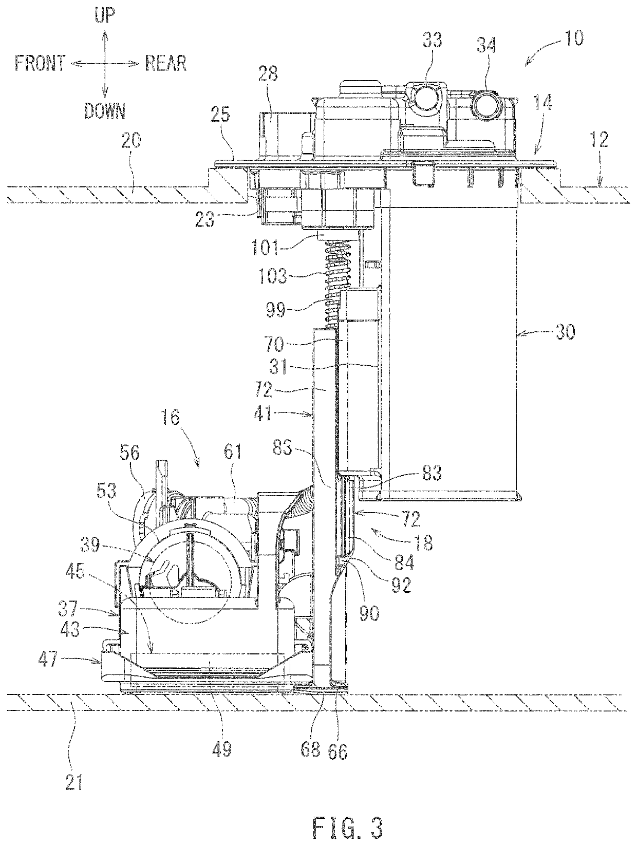
[0022]Hereinafter, one exemplary embodiment for carrying out the present invention will be described with reference to the drawings. A fuel supply device according to the present embodiment serves to supply fuel from within a fuel tank to an engine, wherein the fuel tank is mounted on a vehicle such as an automobile equipped with an engine, such as an internal combustion engine. Each indicated direction, such as the forward, rearward, leftward, rightward, upward and downward directions, as indicated in FIGS. 1 to 4, corresponds to a respective direction of the vehicle upon which the device may be fitted. In particular, the frontward / rearward directions correspond to the vehicle length direction, the leftward / rightward directions correspond to the vehicle width direction, and the upward / downward directions correspond to the vehicle height. The frontward / rearward directions and leftward / rightward directions of the fuel supply device may be oriented in any conceivable direction.

[0023]A...


PUM


Abstract

A fuel supply device includes a flange unit configured to be attached to an upper wall of a fuel tank to close an opening of the fuel tank, a pump unit configured to be disposed within the fuel tank, and a coupling mechanism moveably coupling the pump unit to the flange unit in a vertically slidable manner. The coupling mechanism includes a fixed-side rail member having a rail portion extending vertically from the flange unit, and a movable-side rail member having a channel-groove shaped rail groove extending from the pump unit. The channel-groove shaped rail groove is slidably engaged with the rail portion of the fixed-side rail member. A recess having a semi-circular cross section is formed at a corner of the rail groove of the movable-side rail member.

Description

CROSS-REFERENCE TO RELATED APPLICATIONS[0001]The present application is a 35 U.S.C. § 371 National Phase entry of, and claims priority to, PCT Application No. PCT / JP2017 / 000042, filed Jan. 4, 2017, which claims priority to Japanese Patent Application No. 2016-009524, filed Jan. 21, 2016, both of which are hereby incorporated herein by reference in their entireties for all purposes.STATEMENT REGARDING FEDERALLY SPONSORED RESEARCH OR DEVELOPMENT[0002]Not applicable.BACKGROUND[0003]The present disclosure relates to a fuel supply device for supplying fuel from a fuel tank on a vehicle to an internal combustion engine such as a vehicle engine.[0004]Conventional fuel supply devices have been disclosed in, for example, Japanese Laid-Open Patent Publication No. 2012-184760. The fuel supply device includes a cover-side unit, a pump-side unit, and a coupling mechanism. The cover-side unit is configured to close an opening that is formed on an upper wall of a fuel tank of a vehicle or the like...

Claims


Application Information

Patent Timeline
Patent Type & Authority Patents(United States)
IPC IPC(8): F02M37/10B60K15/03
CPCF02M37/103F02M37/10F02M37/106B60K2015/03243
Inventor FUKUI, TATSUKIYOSHIDA, KOJIIIDA, AKIRAHIGASHI, SHINYATAKEMURA, MORIHIROKARIYA, HIROYASUMORIZONO, TAKEAKIFUJIWARA, TAKUHITONIWA, KENSUKEYAMAUCHI, TAKEHIRO
Owner AISAN IND CO LTD
Why Eureka
Try Eureka