Device for determining the position of an object in space

a technology for determining the position of objects and space, applied in the direction of instruments, navigation instruments, generating/distributing signals, etc., can solve the problems of limiting the freedom of movement of objects and low dynamic accuracy, and achieve the effects of increasing ergonomics, improving dynamic measurement accuracy, and being convenient to us

Active Publication Date: 2020-01-21
OBSCHESTVO S OGRANICHENNOI OTVETSTVENNOSTYU NASTEC
View PDF5 Cites 0 Cited by
  • Summary
  • Abstract
  • Description
  • Claims
  • Application Information

AI Technical Summary

Benefits of technology

[0004]The object of the invention is to create a simple by design, easy to use device for determining the position and orientation of a moving object that differs from the prototype by increased dynamic measurement accuracy, increased ergonomics and enhanced functionality (extensibility and modularity).
[0005]The technical result is to increase the measurement accuracy by eliminating the measurement error of the gravity vector direction caused by the movement of the platform with sensors.
[0006]The elimination of the error in measuring the gravity vector direction is achieved by the fact that the mobile platform with sensors is additionally equipped with a three-component gyroscope, the measurements of which are then used to correct the accelerometer measurements.
[0007]An additional effect achieved with the claimed invention is the elimination of the requirement for a communication line between the computing unit and the power supply.
[0008]The elimination of the requirement of a communication line between the computing unit and the power supply is achieved by the fact that the power supply additionally equipped with a clock generator, which using a given frequency supplies the controlled coil current regulator with a current reversal signal, and the computing unit is additionally equipped with a phase-locked loop unit for the magnetometer clocking and ensuring synchronization of the magnetometer measurement phase with the phase of the magnetic field pulses generated by the inductance coil.

Problems solved by technology

The disadvantages of the prototype can be attributed to low dynamic accuracy due to the presence of measurement errors by the accelerometer of the gravity vector direction caused by the presence of its own acceleration at the platform with sensors as it moves.
In addition, the presence of the communication line between the computing unit and the current stabilizer negatively affects the ergonomic design of the device, and may limit the freedom of movement of the object.

Method used


Image

  • Device for determining the position of an object in space
  • Device for determining the position of an object in space
  • Device for determining the position of an object in space

Examples


Embodiment Construction

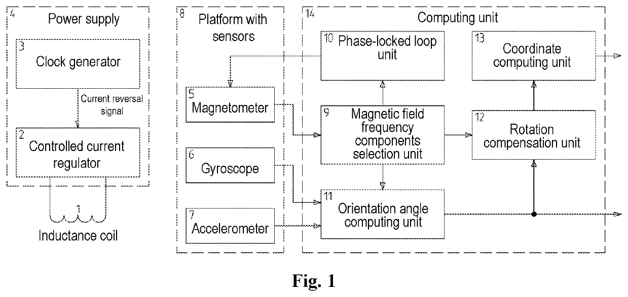
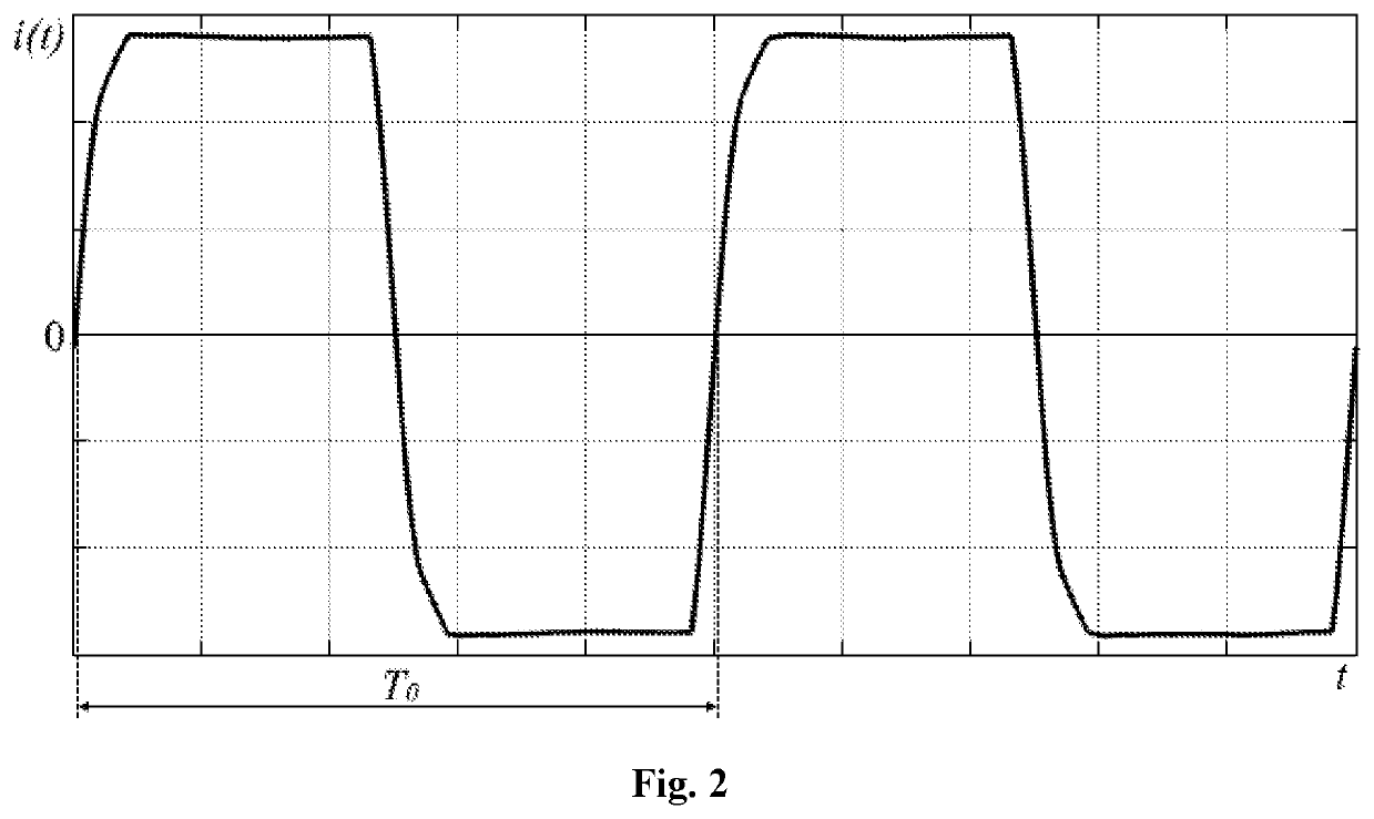
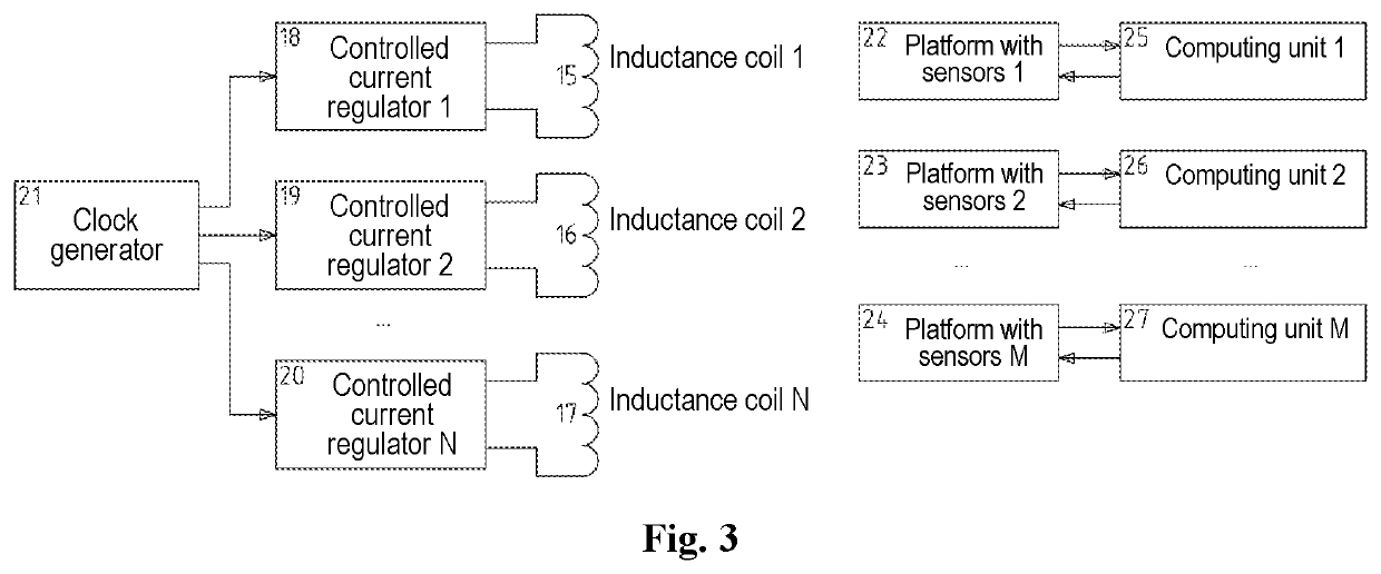
[0021]The claimed device consists of inductance coil 1 (field source) placed stationary in a horizontal plane and connected to controlled current regulator 2, which receives a signal to change the current polarity from clock generator 3 with a given frequency. Controlled current regulator 2 together with clock generator 3 form the power supply of inductance coil 4.

[0022]Digital three-component magnetometer 5, gyroscope 6 and accelerometer 7 are located on platform 8. Platform with sensors 8 is rigidly fixed to the moving object. Magnetometer 5, gyroscope 6 and accelerometer 7 interact with computing unit 14, which contains: magnetic field frequency components selection unit 9; phase-locked loop unit 10; orientation angle computing unit of the platform with sensors 11; rotation compensation unit of the platform with sensors 12; coordinate computing unit of the platform with sensors 13. Wherein the output of magnetometer 5 is connected to the input of magnetic field frequency componen...


PUM


Abstract

This invention relates to a measurement equipment and can be used to create means of measuring coordinates and angular values of an object freely moving in space with six degrees of freedom. The invention can be applied in human-machine interfaces as a coordinate input device, particularly, in training systems, in robotics, in augmented, virtual reality and mixed reality systems. The technical result is to increase the measurement accuracy by eliminating the measurement error of the gravity vector direction caused by the movement of the platform with sensors. There is the claimed device, wherein it comprises an inductance coil placed stationary in a horizontal plane, a power supply of the inductance coil, a computing unit, and a platform with sensors placed on a moving object, including a three-component magnetometer, three-component accelerometer and three-component gyroscope, with the power supply of the inductance coil including a coil current regulator controlled by a clock generator, and the computing unit is arranged with phase-locked loop, ensuring clocking of the magnetometer and synchronization of the magnetometer measurement phase with the phase of magnetic field pulses generated by the inductance coil.

Description

FIELD OF THE INVENTION[0001]This invention relates to a measurement equipment and can be used to create means of measuring coordinates and angular values of an object freely moving in space with six degrees of freedom. The invention can be applied in human-machine interfaces as a coordinate input device, particularly, in training systems, in robotics, in augmented, virtual reality and mixed reality systems, and also in the gaining industry (as manipulators, game controllers, etc.), production sector (systems of positioning industrial equipment working parts, process control), CAD design (input systems, design process control).BACKGROUND OF THE INVENTION[0002]There is known a device for positioning object in space (patent RU2542793, Chernyshov E. S., G01C21 / 08, publ. 27 Feb. 2015). This invention on the essential features set is the closest to the claimed one and adopted for the prototype. The known device consists of an inductance coil (field source), a controlled current regulator,...

Claims


Application Information

Patent Timeline
Patent Type & Authority Patents(United States)
IPC IPC(8): G06F3/0346G01C21/08G01C21/16G01C25/00G01C21/18
CPCG01C25/005G06F3/0346G01C21/18G01C21/08G01C21/165A61B5/1114G01B7/004G06F3/011G06F3/038G06F1/12G06F1/26G06F1/1694G06F2200/1637G01C21/1654Y02A90/30G01D21/02
Inventor CHERNYSHOV, EVGENY SERGEEVICH
Owner OBSCHESTVO S OGRANICHENNOI OTVETSTVENNOSTYU NASTEC
Why Eureka
Try Eureka