
Fouling prevention system for submerged hydraulic cylinders

a technology of anti-fouling and hydraulic cylinder, which is applied in the direction of mechanical equipment, servomotors, transportation and packaging, etc., can solve the problems of cylinders that are prone to be fouled or contaminated, interfere with the operation of the mechanism, and cylinders that require periodic cleaning, repair and/or replacement, etc., and achieve the effect of preventing cylinder contamination

Active Publication Date: 2019-12-31
GOLDEN WILLIAM
View PDF7 Cites 1 Cited by
  • Summary
  • Abstract
  • Description
  • Claims
  • Application Information

AI Technical Summary

Benefits of technology

The system effectively prevents water and contaminant intrusion, reducing maintenance needs and extending the operational life of submerged hydraulic cylinders by eliminating the issues of implosion and ballooning, thus minimizing maintenance and replacement costs.

Problems solved by technology

In such situations, the cylinder mechanism is apt to become fouled or contaminated due to dirt, debris, marine growth, minerals and other contaminants collecting on the cylinder rod.
Over time, this debris can be gradually pulled into the cylinder, which can eventually interfere with operation of the mechanism.
As a result, such cylinders typically require periodic cleaning, repair and / or replacement.
This can be time consuming and expensive and is likely to interrupt use of the hydraulic cylinder mechanism.
Unfortunately, in underwater environments, such boots do not operate in an optimally effective manner.
Conversely, when the cylinder rod retracts and the boot collapses, water previously trapped within the boot causes the boot to balloon.
Such constant and repeated imploding and ballooning of the boot can cause the boot to prematurely deteriorate and eventually fail.
However, this tends to introduce a considerable amount of contaminants into the bellows element, which eventually collect on and interfere with operation of the cylinder rod.
However, water and accompanying minerals, dirt and debris continue to collect on and contaminate the hydraulic cylinder, which can damage the submerged cylinder over extended periods of time.
In order to reduce the contaminants that inevitably foul the cylinder rod, U.S. Pat. No. 8,291,810 also employs a series of scrubbers, which complicate the construction and increase the expense of the protective bellows element considerably.

Method used


Image

  • Fouling prevention system for submerged hydraulic cylinders
  • Fouling prevention system for submerged hydraulic cylinders
  • Fouling prevention system for submerged hydraulic cylinders

Examples


Embodiment Construction

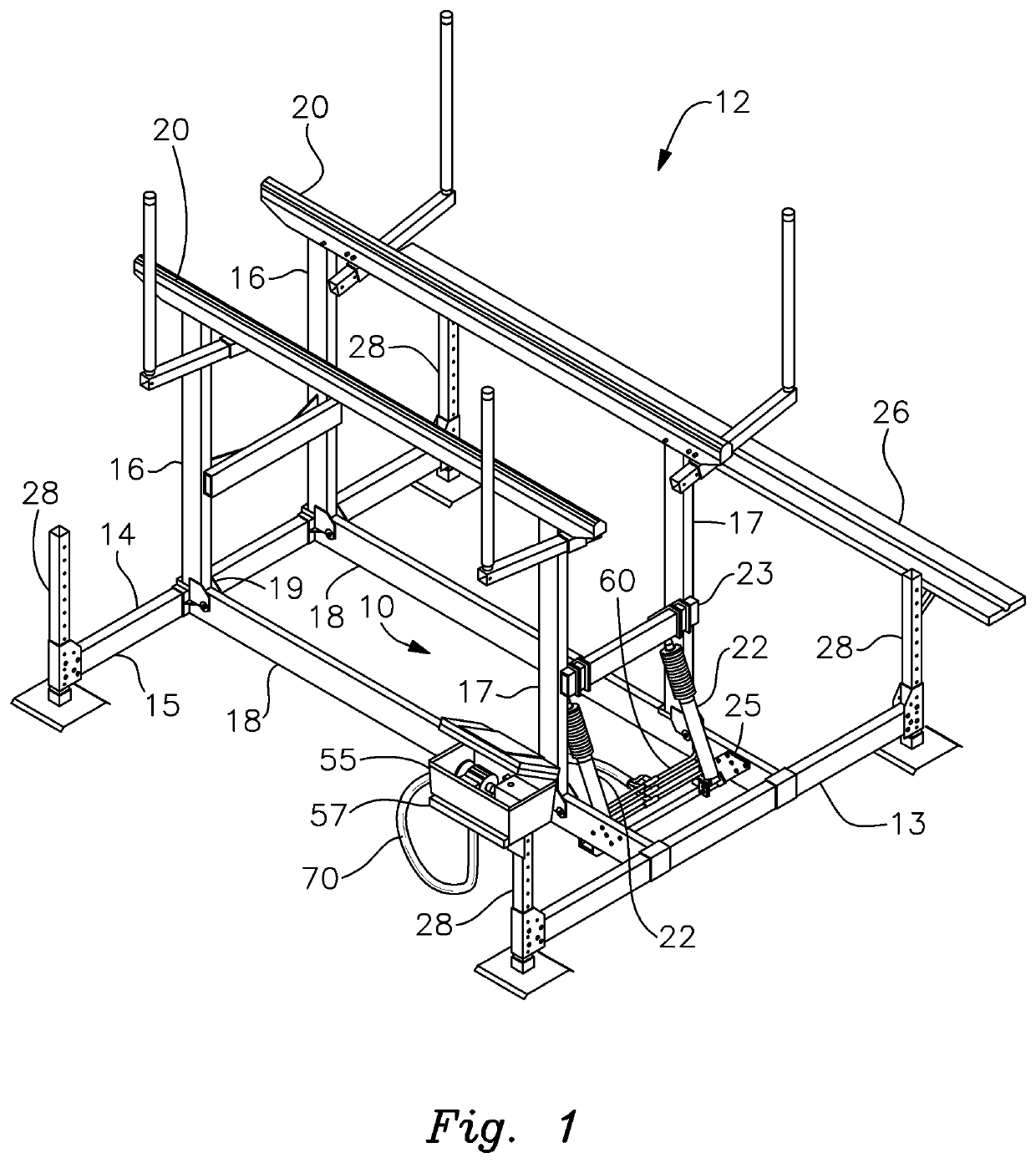
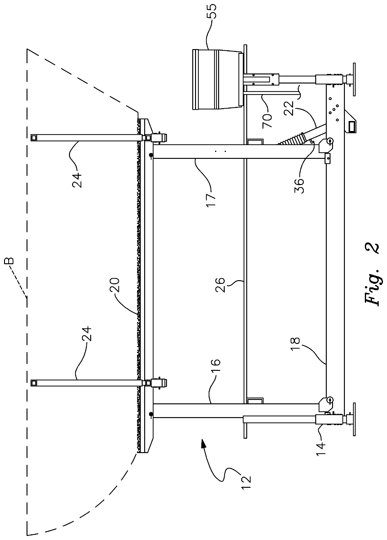
[0025]There is shown in FIG. 1 a fouling prevention system 10 that is incorporated in a hydraulically operated aluminum boat lift 12 in accordance with this invention. The boat lift features a supportive framework 14 that is positioned in a body of water, not shown. Framework 14 is adjustably mounted on supportive stanchions 28, which are themselves mounted on the bottom or floor of the body of water. The framework may be adjusted vertically along stanchions 28 so that the height of boat lift 12 within the body of water may be set as required for a particular vessel.

[0026]Framework 14 includes a pair of generally parallel longitudinal beams 18. These beams extend between forward and rearward transverse beams 13 and 15, where are themselves mounted to and height adjustable along stanchions 28. A first pair of posts 16 are pivotally mounted at their lower ends to respective longitudinal beams 18 proximate one end of framework 14. An opposite second pair of posts 17 are likewise pivota...


PUM


Abstract

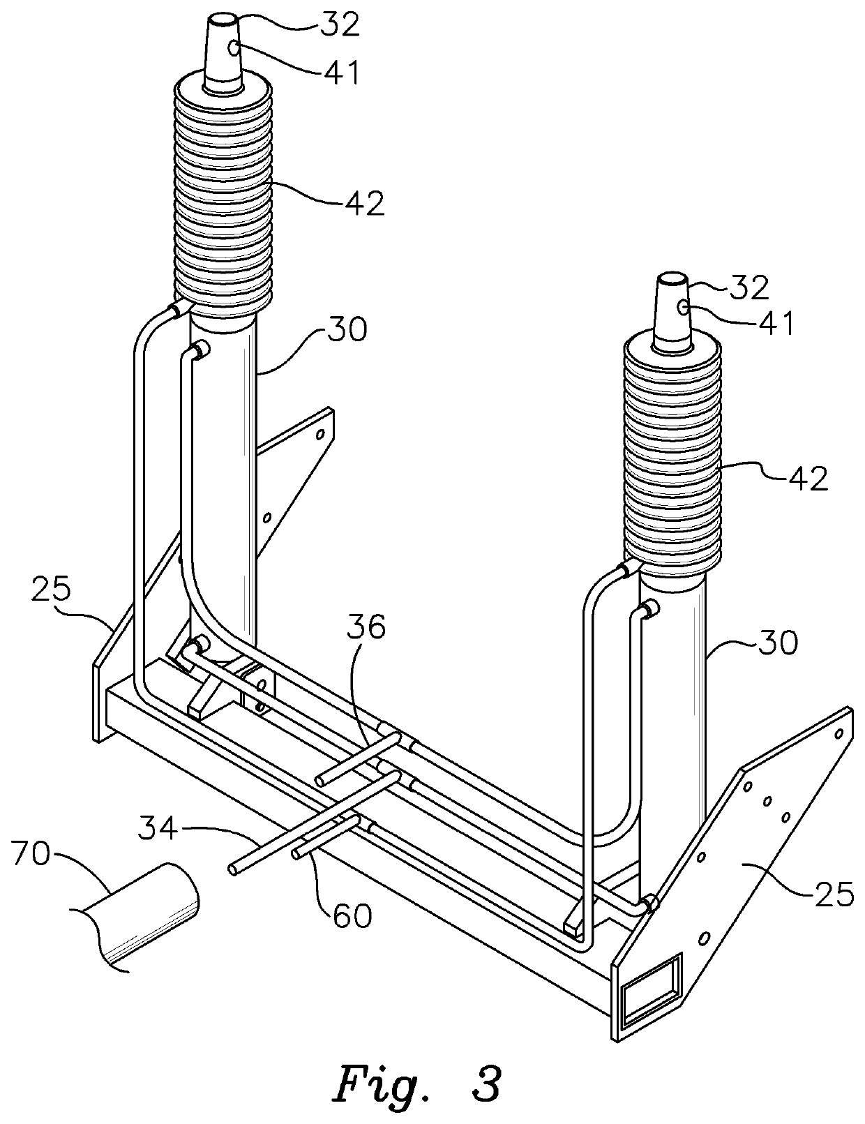
A system for preventing fouling of submerged hydraulic cylinder actuators includes a pneumatic line communicably connected to a protective bellows element surrounding the cylinder rod of the actuator mechanism. As the cylinder rod extends from the cylinder housing of the mechanism and the bellows element expands, filtered air is drawn into the bellows element. Water and accompanying contaminants are prevented from entering the bellows and interfering with operation of the hydraulic actuator mechanism.

Description

RELATED APPLICATION[0001]This application claims the benefit of U.S. Provisional Application Ser. No. 62 / 530,470 filed Jul. 10, 2017.FIELD OF THE INVENTION[0002]This invention relates to a system that prevents fouling and contamination of marine or otherwise submerged hydraulic cylinders and, more particularly, to an anti-fouling system for use with submerged hydraulic cylinders employed in a boat lift.BACKGROUND OF THE INVENTION[0003]Hydraulic cylinders are commonly utilized in underwater, muddy or other fully or partially submerged environments. Such mechanisms are featured, for example, on marine pumps, submerged lifts and particularly boat lifts. In such situations, the cylinder mechanism is apt to become fouled or contaminated due to dirt, debris, marine growth, minerals and other contaminants collecting on the cylinder rod. Over time, this debris can be gradually pulled into the cylinder, which can eventually interfere with operation of the mechanism. As a result, such cylinde...

Claims


Application Information

Patent Timeline
Patent Type & Authority Patents(United States)
IPC IPC(8): F16J3/04F15B11/16F15B15/14B63C1/00
CPCF15B11/16F15B15/1461F15B15/14F15B15/149F16J3/046B63C1/00F15B2211/7107F15B2211/7054F16J15/3208F15B15/20
Inventor GOLDEN, WILLIAM
Owner GOLDEN WILLIAM
Learn More