Bearing damper for cold engine ground starts or in-flight re-starts

a technology for ground-starting or in-flight re-starting of engines, which is applied in the direction of elastic bearings, machines/engines, transportation and packaging, etc., can solve the problems of negative impact on the performance of dampers, and achieve the effect of increasing the leakage of lubricants

Active Publication Date: 2019-12-10
GENERAL ELECTRIC CO
View PDF37 Cites 2 Cited by
  • Summary
  • Abstract
  • Description
  • Claims
  • Application Information

AI Technical Summary

Problems solved by technology

However, when the lubricant is cold (for instance, due to a cold engine or low ambient air temperatures), it is relatively highly viscous and negatively impacts the performance of the damper.

Method used


Image

  • Bearing damper for cold engine ground starts or in-flight re-starts
  • Bearing damper for cold engine ground starts or in-flight re-starts
  • Bearing damper for cold engine ground starts or in-flight re-starts

Examples


Embodiment Construction

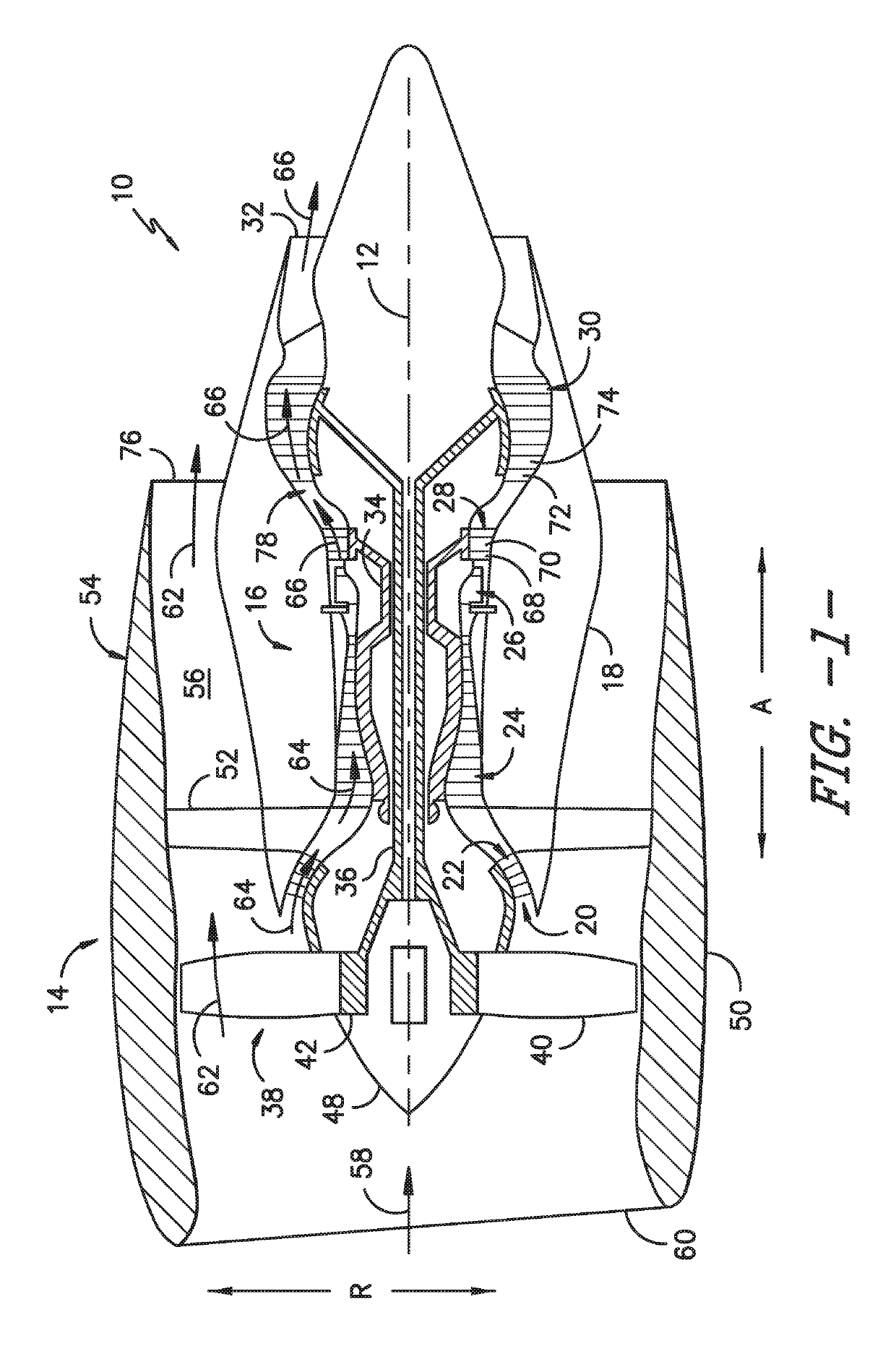
[0013]Reference will now be made in detail to present embodiments of the invention, one or more examples of which are illustrated in the accompanying drawings. The detailed description uses numerical and letter designations to refer to features in the drawings. Like or similar designations in the drawings and description have been used to refer to like or similar parts of the invention. As used herein, the terms “first,”“second,” and “third” may be used interchangeably to distinguish one component from another and are not intended to signify location or importance of the individual components. The terms “upstream” and “downstream” refer to the relative direction with respect to fluid flow in a fluid pathway. For example, “upstream” refers to the direction from which the fluid flows and “downstream” refers to the direction to which the fluid flows. Further, with respect to engine embodiments described herein, the terms “fore” and “aft” generally refer to a position in relation to an ...


PUM


Abstract

Dampers for bearing assemblies of gas turbine engines are provided. For example, a damper comprises a damper housing, a lubricant passage defined in the damper housing, and a valve positioned within the lubricant passage. The lubricant passage includes an inlet and an outlet. In one embodiment, the valve is configured to restrict a flow of lubricant from the inlet into the damper when a reference temperature is below a threshold temperature. In another embodiment, the valve is configured to increase leakage of a lubricant through the outlet when a reference temperature is below a threshold temperature. In other embodiments, the valve is passively actuated and is configured to move within the lubricant passage to control a flow of lubricant from the inlet to the outlet based on a reference temperature.

Description

FIELD[0001]The present subject matter relates generally to gas turbine engines and, more particularly, to bearing dampers for gas turbine engines. Most particularly, the present subject matter relates to bearing dampers with features for managing cold oil at start up or re-starts of a gas turbine engine.BACKGROUND[0002]Gas turbine engines typically include a rotor assembly, a compressor, and a turbine. In turbofan engines, the rotor assembly includes a fan having an array of fan blades extending radially outwardly from a rotor shaft. The rotor shaft, which transfers power and rotary motion from the turbine to both the compressor and the fan, is supported longitudinally using a plurality of bearing assemblies. Known bearing assemblies include one or more rolling elements supported within a paired race. To maintain a rotor critical speed margin, the rotor assembly is typically supported on three bearing assemblies: one thrust bearing assembly and two roller bearing assemblies. The thr...

Claims


Application Information

Patent Timeline
Patent Type & Authority Patents(United States)
IPC IPC(8): F01D25/16F01D25/18F16C27/04
CPCF16C27/045F01D25/164F01D25/18F05D2270/303F05D2270/44F16C2360/23F05D2270/42F05D2260/98F05D2220/323F16C2326/43F05D2240/50F05D2250/232
Inventor ORKISZEWSKI, CHARLES STANLEY
Owner GENERAL ELECTRIC CO
Why Eureka
Try Eureka