Automatic fluid flow controlling device for stopping flow of running fluid

a technology of automatic fluid flow and control device, which is applied in the direction of water supply installation, operating means/releasing devices of valves, functional valve types, etc., can solve the problems of increasing the tension force, affecting the flow of running water, so as to achieve easy adjustment of the height of the liquid level and increase the tension force

Active Publication Date: 2019-12-03
MANDAL SOMJIT
View PDF8 Cites 0 Cited by
  • Summary
  • Abstract
  • Description
  • Claims
  • Application Information

AI Technical Summary

Benefits of technology

[0010]Another object of the present invention is to develop an automatic fluid flow controlling device for stopping flow of the running liquid when the liquid flow exceed a certain flow rate which would be reliable in operation, cheap and easy to fabricate.
[0027]According to another aspect in the present device for flow control of liquid in pipelines to various utility fluid outlets, the maximum flow rate can be controlled by varying the thickness of the first magnet or the washer on top of the bottom outlet or number of the washer.
[0034]said flexible connection enabling placing the weight on any vessel and the like for collection of liquid / water to a defined level such that upon filling of the vessel level with desired liquid / water the upward force of the water on the weight allowing the hinged second magnet to move closer to said flow controlling first magnet supported with respect to said ferrous plate at a supporting stem end and pull and place the said flow controlling first magnet on said outflow opening of said bottom chamber to block further release of liquid / water into said vessel and the like.
[0039]According to another aspect in the present device for flow control of liquid in pipelines to various utility fluid outlets, the second magnet is held in a distance from the first magnet within their magnetic force of attraction using a minimal tensile force produced by the weight of the bobbin and when the liquid level in the vessel reaches the bobbin, buoyancy force reduce the weight causing the second magnet to move towards the first magnet which rapidly increases tension force between the two magnets and causing the attraction force between the first magnet and second magnet exceeds the attraction force between ferrous plate and the first magnet and thus the first magnet moves towards the direction of the second magnet away from the ferrous plate and fixes itself with the washer locking the outflow opening of the bottom chamber to stop the liquid outflow.
[0040]According to another aspect in the present device for flow control of liquid in pipelines to various utility fluid outlets, height of the liquid level can be adjusted easily by adjusting the length of a freely suspended string which can be winded up.
[0050]According to another aspect in the present device for flow control of liquid in pipelines to various utility fluid outlets, wherein resuming flow of the liquid after stopping flow of the running liquid by involving the compressive force means facilitates comprising

Problems solved by technology

In the modern civilization, the excessive use or consumption of water from running tap in houses, railway stations, hotels and other public and industrial establishments is a serious problem considering the limited resource of useable water.
Modern float valve based water overfilling preventing device are getting smaller day by day but they are still bulky and they have lack of flexibility.
The main drawback in the modern float valve based water overfilling preventing device is that they need to be attached with the container or vessel wall and has limited range of adjustable fluid height.

Method used


Image

  • Automatic fluid flow controlling device for stopping flow of running fluid
  • Automatic fluid flow controlling device for stopping flow of running fluid
  • Automatic fluid flow controlling device for stopping flow of running fluid

Examples


Embodiment Construction

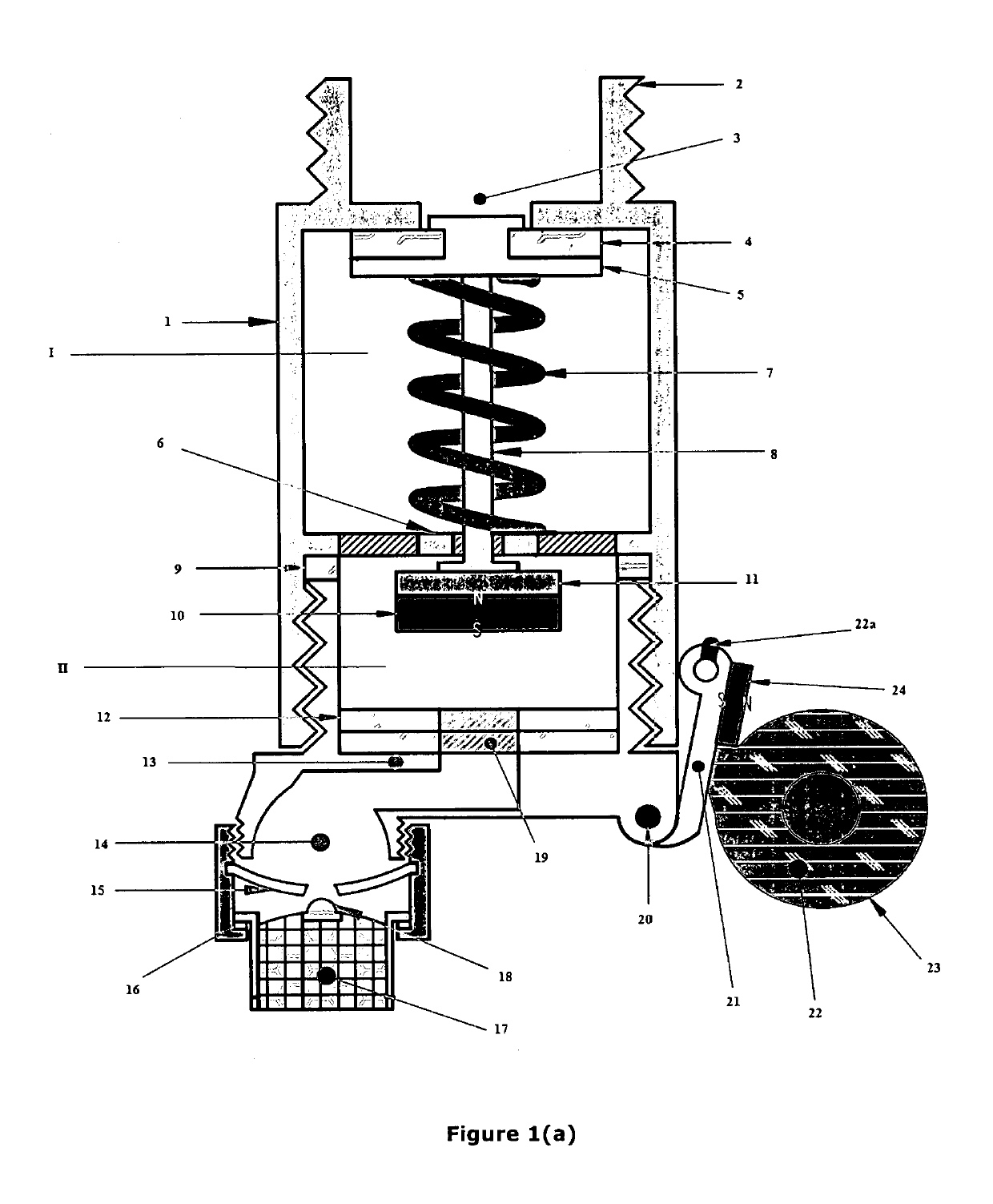
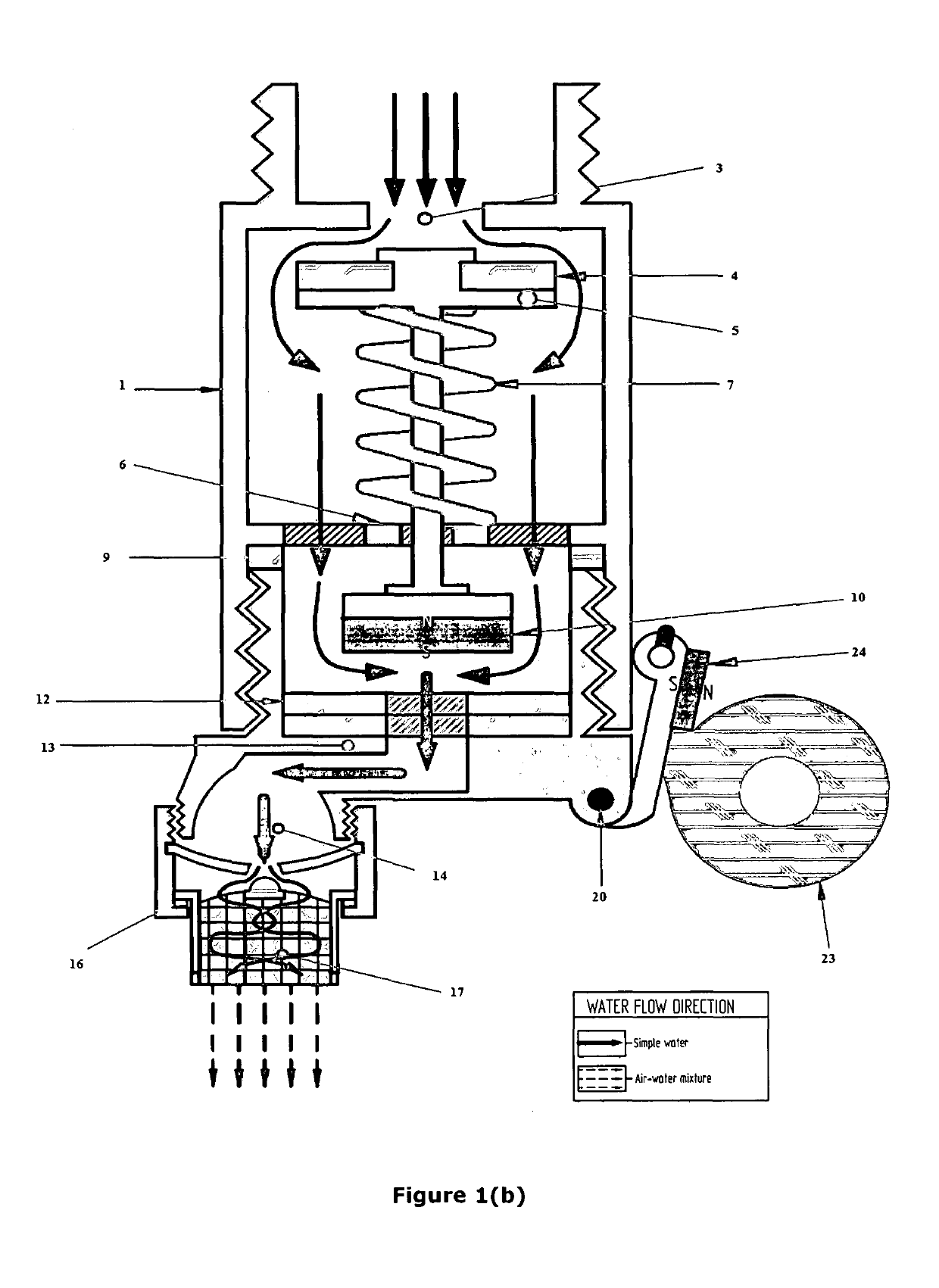
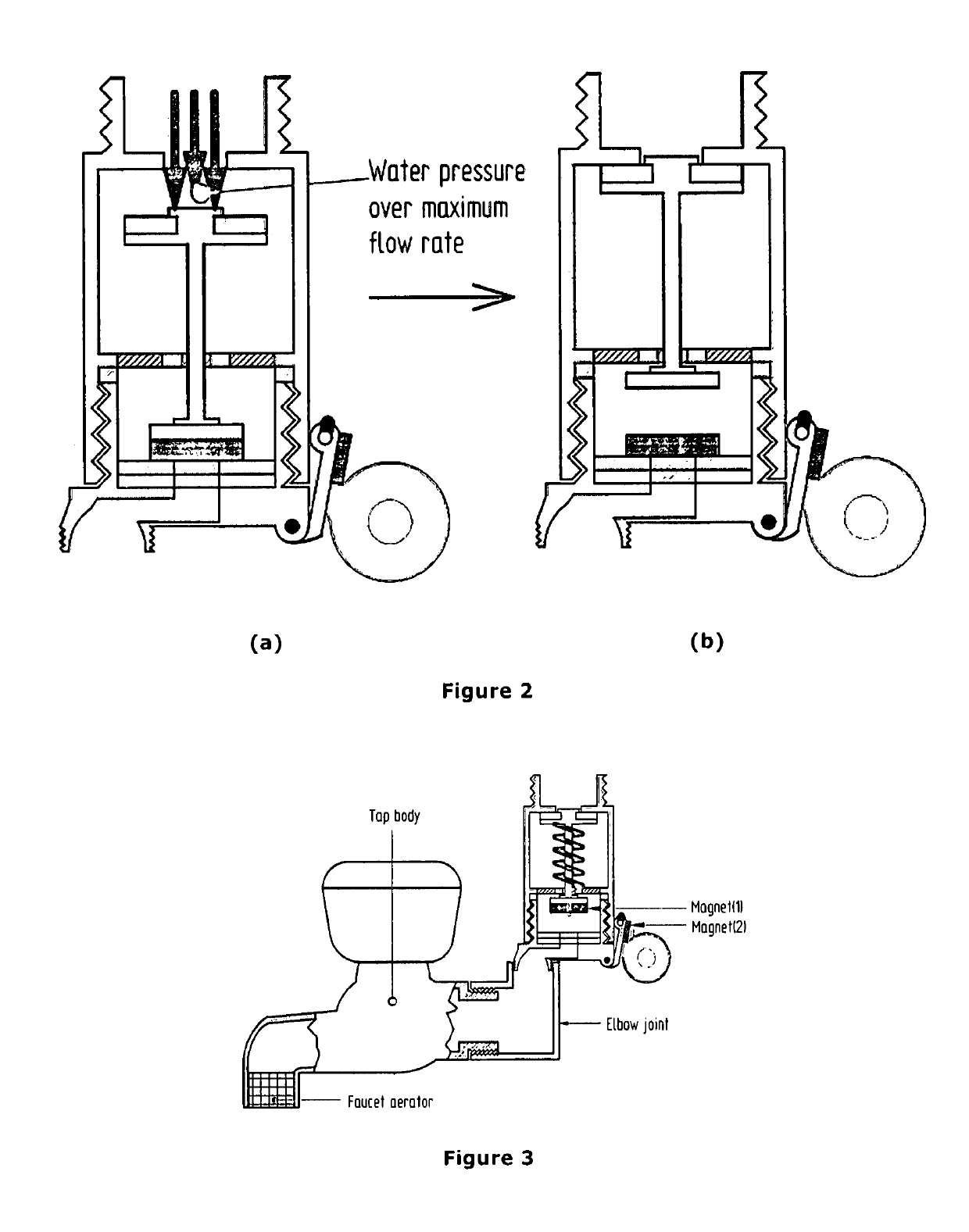
[0068]The present invention discloses a device for flow control of fluid in pipelines to various utility fluid outlets like water taps and the like by blocking fluid flow from pipeline to said utility fluid outlet when the flow exceeds a predetermined flow rate. In other word, the present invention discloses an automatic fluid flow controlling device for restricting or stopping flow of the fluid medium running through the guiding means or the tubing system when fluid flow exceed a certain flow rate as well as stopping flow of the running liquid flow when liquid level in the vessel wherein the running liquid is being delivered reaches a certain height.

[0069]Reference is first invited from the accompanying FIG. 1(a) which shows a preferred embodiment of the automatic flow controlling device for stopping flow of the running fluid when fluid flow exceed a certain flow rate. As shown in the accompanying FIG. 1, the main structure of the present device includes a housing body (1) for encl...


PUM


Abstract

The present invention discloses a device for flow control of fluid in pipelines to various utility fluid outlets like water taps and the like by blocking fluid flow from pipeline to said utility fluid outlet when the flow exceeds a predetermined flow rate. In other word, the present invention discloses an automatic fluid flow controlling device for restricting and / or stopping flow of the fluid medium running through the guiding means or the tubing system when fluid flow exceed a certain flow rate as well as stopping flow of the running fluid flow when fluid level in the vessel wherein the running fluid is being delivered reaches a certain height.

Description

FILED OF THE INVENTION[0001]The present invention relates to a technology for automatically controlling flow of running fluid. In particular, the present invention is directed to develop an automatic fluid flow controlling device adapted for stopping flow of the running fluid when the fluid flow exceed a certain flow rate as well as stopping flow of the running fluid flow when fluid level in a vessel wherein the running fluid is being delivered reaches a certain height.BACKGROUND OF THE INVENTION[0002]There are many instances wherein flow of a fluid medium running through a guiding means or tubing systems needs to be regulated to restrict overuse / wastage of the fluid. Desirably, such automated control of flow of the running fluid should maintain an initially set flow rate of the running fluid and automatically stop the flow of the running fluid upon detecting the flow rate exceeding the initially set flow rate.[0003]The presently available automated system for controlling flow of fl...

Claims


Application Information

Patent Timeline
Patent Type & Authority Patents(United States)
IPC IPC(8): E03B1/02E03D1/32F16K31/20F16K31/22F16K31/08E03B7/07F16K17/12F16K15/06E03B1/04F16K17/34
CPCF16K31/20F16K15/063E03B1/02F16K17/12E03B1/04E03B7/078F16K17/34F16K31/084E03D1/32F16K31/086E03B7/075F16K31/22E03B7/071E03B1/042E03B7/07E03B7/077F16K31/06F16K31/08
Inventor MANDAL, SOMJIT
Owner MANDAL SOMJIT
Why Eureka
Try Eureka