Method for operating an inductive conductivity measuring device and respective inductive conductivity measuring device

a technology of inductive conductivity and measuring device, which is applied in the direction of resistance/reactance/impedence, fluid resistance measurement, instruments, etc., can solve the problem of impaired accuracy of analog electronic circuit, and achieve the effect of improving the accuracy of a medium conductivity determination

Active Publication Date: 2019-11-26
KROHNE MESSTECHNICK GMBH & CO KG
View PDF7 Cites 0 Cited by
  • Summary
  • Abstract
  • Description
  • Claims
  • Application Information

AI Technical Summary

Benefits of technology

[0006]Thus, the object of the invention is to provide a method for operating an inductive conductivity measuring device and to provide an inductive conductivity measuring device, in which the accuracy of a determination of a conductivity of a medium is improved compared to the prior art.
[0012]The method according to the invention has the advantage over the method known from the prior art that the determination of the conductivity of the medium is more accurate. The higher accuracy is a result of a frequency of an alternating signal being determined instead of amplitudes of variables. It has been shown that with the same technical effort and, thus, the same costs, the determination of a frequency can be implemented more accurately than the determination of an amplitude.

Problems solved by technology

However, a problem in the determination of amplitudes using analog electronic circuits is that the accuracy of the determination of an amplitude, and thus, also the accuracy of the determination of a conductivity of a medium depends on the accuracy of the electronic circuit.
The accuracy of an analog electronic circuit is impaired by drifts and tolerances of the components of the electronic circuit.

Method used


Image

  • Method for operating an inductive conductivity measuring device and respective inductive conductivity measuring device
  • Method for operating an inductive conductivity measuring device and respective inductive conductivity measuring device
  • Method for operating an inductive conductivity measuring device and respective inductive conductivity measuring device

Examples


Embodiment Construction

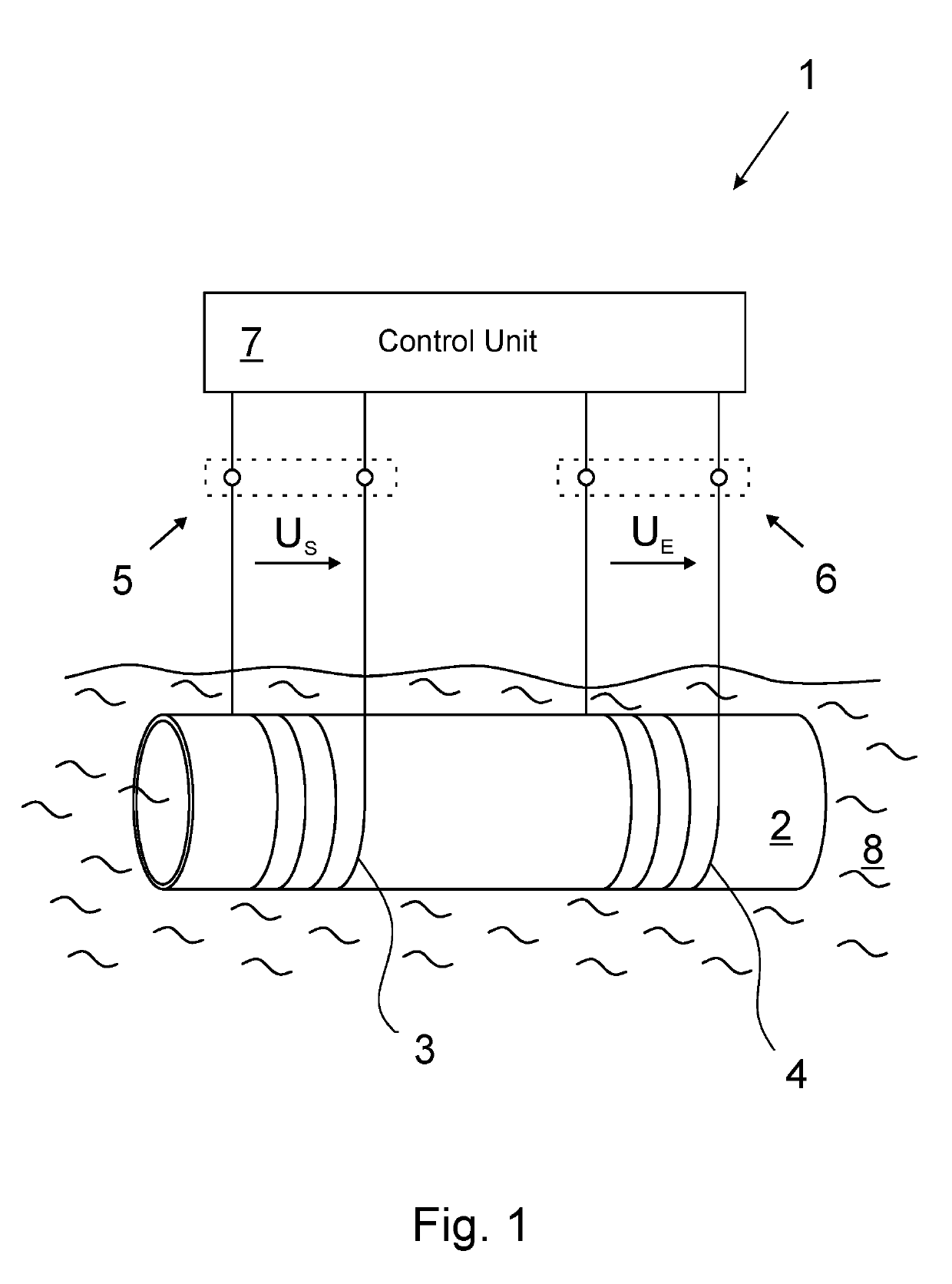
[0026]FIG. 1 shows the inductive conductivity measuring device 1. The inductive conductivity measuring device 1 has the hollow-cylindrical carrier 2, on which the transmitting coil 3 and the receiving coil 4 are arranged. The transmitting coil 3 and the receiving coil 4 are arranged on the hollow cylindrical carrier 2 by being wound around the hollow cylindrical carrier 2, wherein the transmitting coil 3 has the number NS of turns and the receiving coil 4 has the number NE of turns. Furthermore, the transmitting coil 3 has the input 5 and the receiving coil 4 has the input 6. The inductive conductivity measuring device 1 also has the control unit 7. The control unit 7 is designed to control the transmitting coil 3 and the receiving coil 4, which is why the control unit 7 is also electrically connected to the input 5 of the transmitting coil 3, on the one hand, and to the input 6 of the receiving coil 4, on the other hand.

[0027]The hollow cylindrical carrier 2 having the transmitting...


PUM


Abstract

A method for operating an inductive conductivity measuring device that has a transmitting coil with an input and a receiving coil, the transmitting coil and the receiving coil being inductively coupled to one another by an electrically conductive medium. An electrical preset alternating signal is generated and fed to the input of the transmitting coil. The method for operating an inductive conductivity measuring device is improved in that a frequency of a preset alternating signal is varied in a frequency interval, in the frequency interval, a frequency-dependent minimum input impedance at the input of the transmitting coil is determined using a response alternating signal, a minimum frequency of the response alternating signal is determined at the minimum input impedance at the input of the transmitting coil, and a conductivity of the medium is determined using the minimum frequency of the response alternating signal.

Description

BACKGROUND OF THE INVENTIONField of the Invention[0001]The invention relates, on the one hand, to a method for operating an inductive conductivity measuring device. The conductivity measuring device has a transmitting coil and a receiving coil for carrying out the method and the transmitting coil, in turn, has an input. The transmitting coil and the receiving coil are inductively coupled to one another by an electrically conductive medium. In the method, an electrical preset alternating signal is generated and supplied to the input of the transmitting coil.[0002]The invention relates, on the other hand, to an inductive conductivity measuring device. The conductivity measuring device likewise has a transmitting coil, a receiving coil, and a control unit for, among other things, controlling the transmitting coil and the receiving coil. In turn, the transmitting coil has an electrical input. The control unit is thereby designed to generate an electrical preset alternating signal and to...

Claims


Application Information

Patent Timeline
Patent Type & Authority Patents(United States)
IPC IPC(8): G01R31/00G01R27/26
CPCG01R27/2611G01N27/025G01R27/22
Inventor GLASMACHERS, HOLGERMERTMANN, PHILIPP
Owner KROHNE MESSTECHNICK GMBH & CO KG
Why Eureka
Try Eureka