
Hydrogen sensor, hydrogen detection system employing the same, and electrical device with a hydrogen detection system

a hydrogen detection and sensor technology, applied in measurement devices, scientific instruments, instruments, etc., can solve the problems of form decomposition gasses, inability to monitor the status of the current electrical transformer, and the failure of the most modern electrical transformer in the power grid, so as to avoid electrical interference, and reduce the cost of monitoring.

Active Publication Date: 2019-11-26
ABB (SCHWEIZ) AG
View PDF7 Cites 0 Cited by
  • Summary
  • Abstract
  • Description
  • Claims
  • Application Information

AI Technical Summary

Benefits of technology

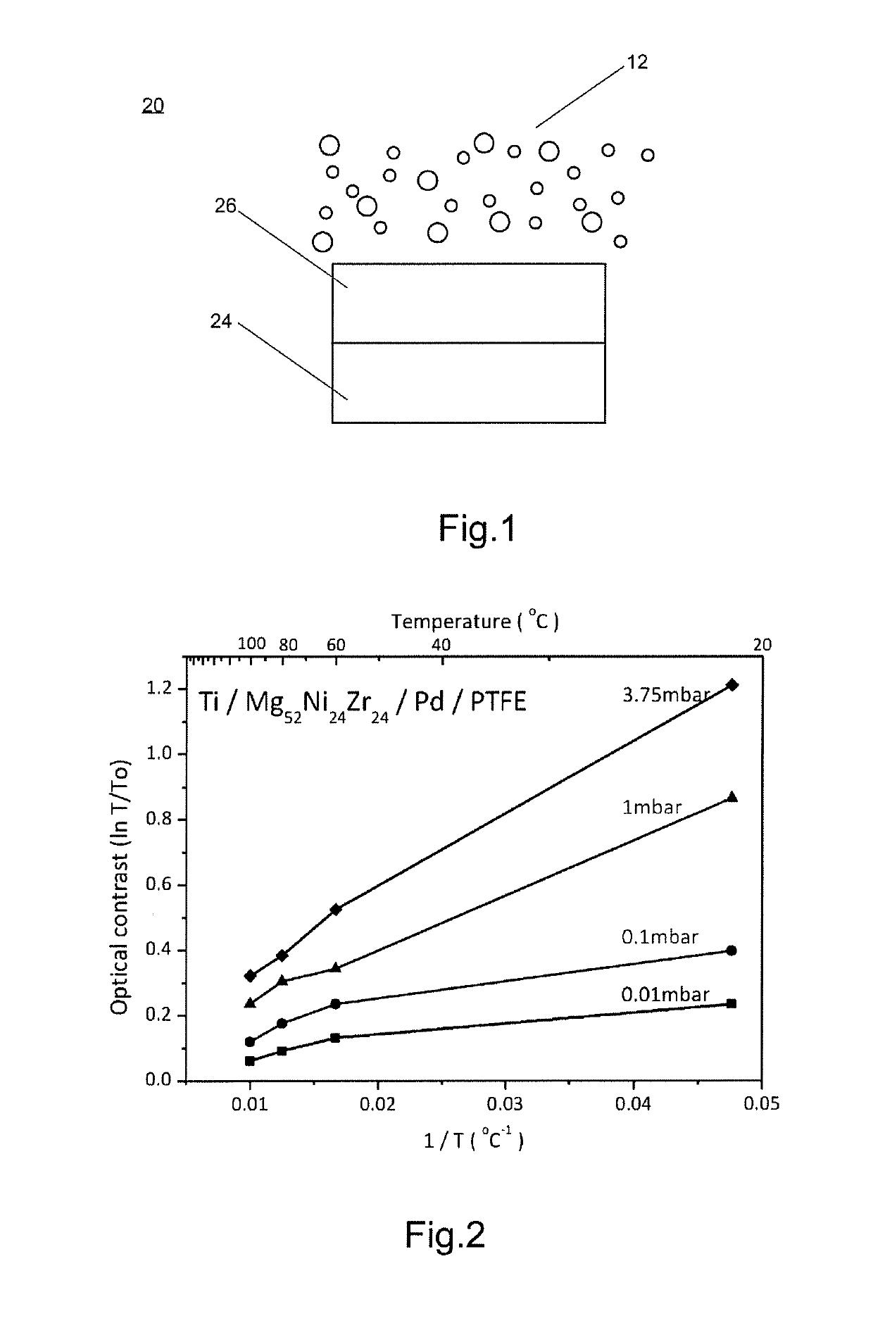
The provided optical sensor and detection system using it provide a reliable and minimalistic hardware setup for monitoring the condition of electrical equipment and its insulation liquid. The system avoids electrical interference and is safe due to the absence of electrical contacts and conductors in the sensing area. It is simple, cost-effective, and robust, and can be extended with many fiber sensors simultaneously. The sensor assembly is advantageous for monitoring oil-filled transformers. The provided metal-alloy hydride system has a large optical change and an inclined pressure transmission isotherm in the temperature and pressure range of interest. The sensor and detection system are stable with respect to cycling and in time, within the temperature range of interest.

Problems solved by technology

Faults inside the electrical equipment as well as degradation of the insulation liquid and of other insulation components such as insulation paper provided within the electrical equipment can form decomposition gasses which mainly dissolve into the liquid.
It is important to detect such faults, errors and degradations early, since especially transformers are important components of the electrical grid, and their failure can be very costly.
Most modern electrical transformers in power grids are still not equipped with on-line or real-time monitoring devices for such gasses.
This monitoring method is time consuming, lacks continuity, has the risk of human error and is highly priced.
Even if this costly method is carried out more frequently, there are several possible sources for error in the process, for example changes in the chemical and physical properties of the probe during the transport between the point in time when the probe is drawn, and the moment when the gas content is actually determined in a laboratory.
Also, this method does not provide any information on where a fault occurred in the transformer.
These sensing techniques usually require a complicated gas separation system that adds complexity and cost to the sensor design and calibration.
Thus, these devices are generally cumbersome and expensive.
Additionally, some of these monitoring techniques suffer from cross-sensitivity towards other gases present in the oil, which additionally makes the results less reliable.
Therefore, even advanced transformers, i.e. those equipped with a dedicated on-line gas monitoring system, are often still additionally and periodically verified with expensive laboratory tests to reassure the accuracy of the on-line gas monitoring system.
However, such known configurations leave great room for improvement.
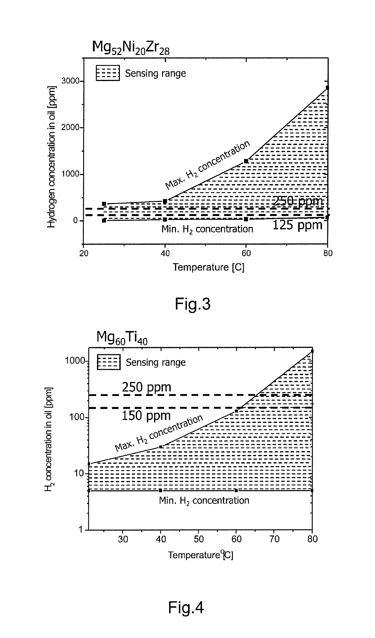
Other optical sensors do exhibit a continuous change of their optical properties with growing hydrogen concentrations in the oil, however they lack sensitivity in certain temperature and hydrogen concentration regimes which would be desirable for enabling monitoring the hydrogen concentration at a broad range of possible operating conditions of transformers.
At lower operating temperatures, which are much more significant for standard transformer operation, the effective measurement ranges for hydrogen concentrations are much smaller (and the sensitivity lower) with the known technology, so that it is improvable for the detection of transformer faults.
In addition, often these metal-hydride systems do not show a reproducible optical behavior upon hydrogen cycling as required, which results in an instable response of the sensor over time.

Method used


Image

  • Hydrogen sensor, hydrogen detection system employing the same, and electrical device with a hydrogen detection system
  • Hydrogen sensor, hydrogen detection system employing the same, and electrical device with a hydrogen detection system
  • Hydrogen sensor, hydrogen detection system employing the same, and electrical device with a hydrogen detection system

Examples


Embodiment Construction

[0030]As used herein, metal alloys defined by a formula with atomic percentage values typically adding to 100 percent, such as, for example, Mg52Ni20Zr28, are meant to also include substances with a composition deviating from that with the exact numbers provided. Typically, alloys having a composition wherein each number, independently from each other, has a tolerance of + / −15 percent, are still regarded to fall under the metal alloy provided by provision of the exact formula, such as the example above, also if the single numbers do not add up to 100 in total. Also, as used herein, such alloys may comprise further, non-named substances such as chemical elements of smaller amounts, such as up to about 2 percent each, but not more than about 10 percent in total.

[0031]As used herein, the term “fluid” is intended to be both representative for gases and liquids. It is, however, mainly used to be representative of an insulation liquid, particularly an oil, which is part of the insulation ...


PUM

PropertyMeasurementUnit
temperatureaaaaaaaaaa
operating temperatureaaaaaaaaaa

Abstract

An optical sensor for detecting hydrogen in a fluid in physical contact with the sensor is provided. The sensor includes an optical fiber, wherein an end portion of the optical fiber is coated with a multilayer including: a sensing layer, including a film of an alloy, the alloy including Mg, Ni, and M, wherein M is at least one of Zr, Ta, and Hf, and wherein the alloy has the composition MgxNiyMz, and wherein x is from 40 to 60, y is from 10 to 40, and z is from 10 to 40, and a catalyst layer including Pd. Further, a detection system for hydrogen, including such an optical sensor, and an electrical device having such a detection system are provided.

Description

FIELD OF THE INVENTION[0001]Aspects of the present disclosure relate to a hydrogen sensor, a hydrogen detection system employing the same, and to an electrical device including such a detection system. In particular, aspects relate to a hydrogen sensor and a hydrogen detection system with such a sensor for liquid-filled electrical equipment, and more particularly to oil-filled electrical transformers having such hydrogen detection systems and hydrogen sensors.BACKGROUND OF THE INVENTION[0002]Insulation-liquid-filled electrical equipment, such as oil-filled shunt reactors, bushings, and especially transformers such as power and distribution transformers, are filled with insulation liquid, in particular oil, for cooling and electrical insulation purposes. Faults inside the electrical equipment as well as degradation of the insulation liquid and of other insulation components such as insulation paper provided within the electrical equipment can form decomposition gasses which mainly di...

Claims


Application Information

Patent Timeline
Patent Type & Authority Patents(United States)
IPC IPC(8): G01N33/28G01N21/77G01N21/75
CPCG01N33/2841G01N21/7703G01N2021/7773G01N2201/088G01N2021/772
Inventor VAN MECHELEN, JACOBUS LODEVICUS MARTINUSPANELLA, BARBARAGARCIA, MERCEDES VICTORIAWESTERWAAL, RUUD JOHANNESDAM, BERNARD
Owner ABB (SCHWEIZ) AG
Learn More