Compressed air energy storage and power generation method and compressed air energy storage and power generation device

a technology of compressed air and energy storage, which is applied in the direction of engine starters, electrical storage systems, greenhouse gas reduction, etc., can solve the problems of power generation output largely decreasing, power generation output fluctuations, so as to achieve high discharge/discharge efficiency as a whole.

Active Publication Date: 2019-11-19
KOBE STEEL LTD
View PDF12 Cites 2 Cited by
  • Summary
  • Abstract
  • Description
  • Claims
  • Application Information

AI Technical Summary

Benefits of technology

[0025]In accordance with the present invention, in the case of smoothing the renewable energy by the compressed air energy storage and power generation device, even when the amount of air stored in the accumulator tank fluctuates from the reference storage value, the charge / discharge efficiency as a whole can be highly maintained. Moreover, the pressure range of the accumulator tank, in which the compressed air energy storage and power generation device can operate by means of the predetermined rated input or rated output, can be expanded.

Problems solved by technology

For example, the power generation cannot be performed at night, and the power generation output largely decreases on rainy and cloudy days.
For example, in such a power generation facility such as a wind farm in which a plurality of wind turbines are gathered, the power generation outputs of the respective wind turbines are added to one another, whereby short-cycle fluctuations of the power generation can be smoothed; however, the fluctuations of the power generation output thereof cannot be avoided when the power generation output is viewed as a whole.

Method used


Image

  • Compressed air energy storage and power generation method and compressed air energy storage and power generation device
  • Compressed air energy storage and power generation method and compressed air energy storage and power generation device
  • Compressed air energy storage and power generation method and compressed air energy storage and power generation device

Examples


first embodiment

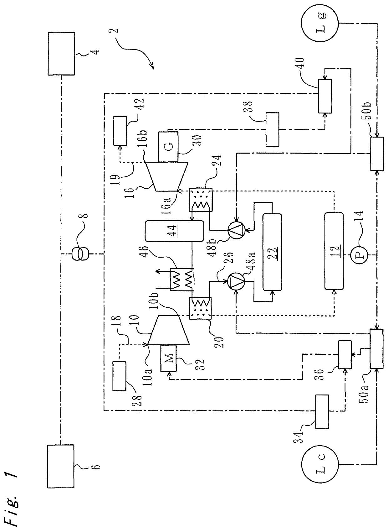
[0034]FIG. 1 shows a schematic configuration diagram of a compressed air energy storage (CAES) power generation device 2. In the case of generating power by using renewable energy, the CAES power generation device 2 of this embodiment smoothes a fluctuation of an output to a power system 4 as a demand destination, and in addition, outputs power matched with a fluctuation of demand power in the power system 4. The CAES power generation device 2 smoothes power, which is supplied from a power plant 6 by renewable energy, such as a wind power plant and a solar power plant, via a power receiving / transmitting facility 8 composed of a transformer and the like, and then outputs the power to the power system 4 as the demand destination.

[0035]Referring to FIG. 1, a description will be made of a configuration of the CAES power generation device 2.

[0036]The CAES power generation device 2 includes an air path and a heat medium path. A compressor 10, an accumulator tank 12 and an expander 16 are ...

second embodiment

[0075]FIG. 7 shows a schematic diagram of a CAES power generation device 2 of a second embodiment. The CAES power generation device 2 of this embodiment is substantially similar to that of the first embodiment in FIG. 1 except that pluralities of the compressors 10, the expanders 16 and heat medium tanks 22a and 22b are installed, and that such constituents are housed in containers 52a to 52c. Hence, a description of portions similar to those shown in FIG. 1 will be omitted. Moreover, since FIG. 7 is a schematic diagram, not all constituents of the CAES power generation device 2 are illustrated.

[0076]Referring to FIG. 7, the CAES power generation device 2 of this embodiment includes three compressors 10 and four expanders 16. The three compressors 10 are fluidly connected in parallel to one another, and the four expanders 16 are also fluidly connected in parallel to one another. The number of compressors 10 and the number of expanders 16, which are to be driven, can be changed in re...


PUM


Abstract

In a compressed air energy storage and power generation device, a compressed air energy storage and power generation method defines, as a reference storage value, a storage value indicating that a storage amount of air in an accumulator tank is in a predetermined intermediate state. At the reference storage value, at least one of a motor and a generator rotates at a rated rotation speed. When a storage value indicating a current storage amount in the accumulator tank is larger than the reference storage value, at least one of the motor and the generator is controlled to rotate at equal to or less than the rated rotation speed. When the storage value indicating the current storage amount in the accumulator tank is smaller than the reference storage value, at least one of the motor and the generator is controlled to rotate at equal to or more than the rated rotation speed and equal to or less than a maximum permissible rotation speed.

Description

CROSS-REFERENCE TO RELATED APPLICATIONS[0001]This is a national phase application in the United States of International Patent Application No. PCT / JP2016 / 063578 with an international filing date of May 2, 2016, which claims priority of Japanese Patent Application No. 2015-101283 filed on May 18, 2015 the contents of which are incorporated herein by reference.TECHNICAL FIELD[0002]The present invention relates to a compressed air energy storage and power generation method and a compressed air energy storage and power generation device.BACKGROUND ART[0003]In power generation using solar energy, such as solar power generation and solar thermal power generation, a power generation output thereof is affected by conditions of sunshine of that day, and fluctuates to a large extent. For example, the power generation cannot be performed at night, and the power generation output largely decreases on rainy and cloudy days. Moreover, when the conditions of sunshine from dawn to sunset are such c...

Claims


Application Information

Patent Timeline
Patent Type & Authority Patents(United States)
IPC IPC(8): F02C6/16F01D19/00F02C9/24F02C1/05F02C7/143
CPCF02C1/05F02C6/16F02C9/24F01D19/00Y02E60/15F02C7/143F02C1/04F05D2260/211F05D2270/02F01D17/08F05D2270/304F05D2270/301F05D2270/312Y02E50/10Y02E70/30Y02E60/16H02J15/006
Inventor MATSUKUMA, MASAKISARUTA, HIROKISAKAMOTO, KANAMI
Owner KOBE STEEL LTD
Why Eureka
Try Eureka