
High-frequency power supply device, and control method for high-frequency power supply device

a technology of high-frequency power supply and control method, which is applied in the direction of electrical discharge tubes, plasma techniques, electrical apparatus, etc., can solve the problems of impedance fluctuation and the problem of impedance matching according to this matching circuit, so as to reduce the time required and minimize the reflection coefficient and/or the reflected power

Active Publication Date: 2019-11-12
KYOSAN ELECTRIC MFG CO LTD
View PDF20 Cites 0 Cited by
  • Summary
  • Abstract
  • Description
  • Claims
  • Application Information

AI Technical Summary

Benefits of technology

The present invention aims to solve the problem of conventional impedance mismatch in RF power supply devices during frequency sweeps. It proposes a method to minimize reflection coefficient and reflected power by specifying the frequency sweep direction that allows them to move to a minimum. This reduces the time required to detect the optimal frequency. The invention also compensates for phase shift due to the transmission line by adding a phase to the output phase state. Overall, this approach improves the efficiency of impedance matching in RF power supply devices.

Problems solved by technology

Variation in the state of electrical discharge of the load may cause fluctuation of impedance.
It has been pointed out that the impedance matching according to this matching circuit has a problem, since it is difficult to respond to abrupt impedance variation.

Method used


Image

  • High-frequency power supply device, and control method for high-frequency power supply device
  • High-frequency power supply device, and control method for high-frequency power supply device
  • High-frequency power supply device, and control method for high-frequency power supply device

Examples


Embodiment Construction

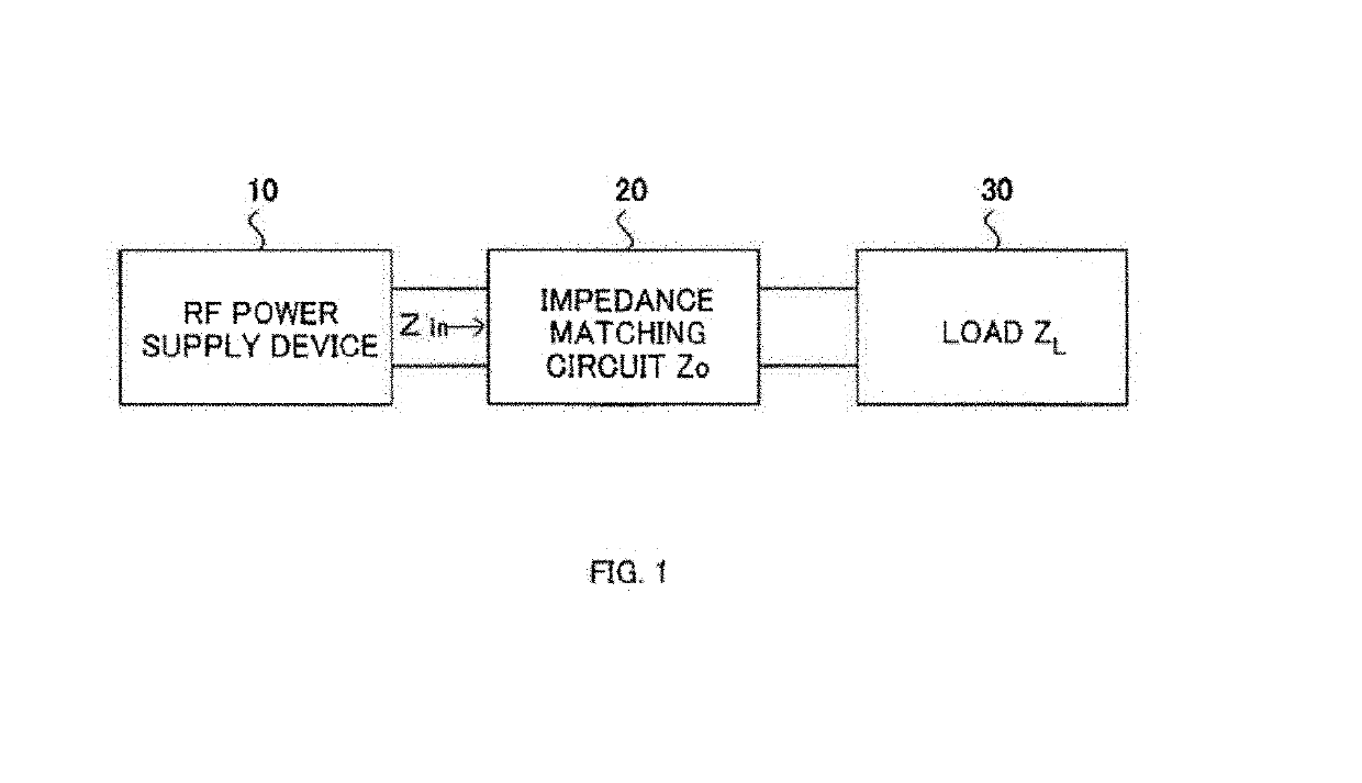
[0076]With reference to FIGS. 1 to 19, there will be described an RF power supply device, and a method of controlling the RF power supply device according to the present invention.

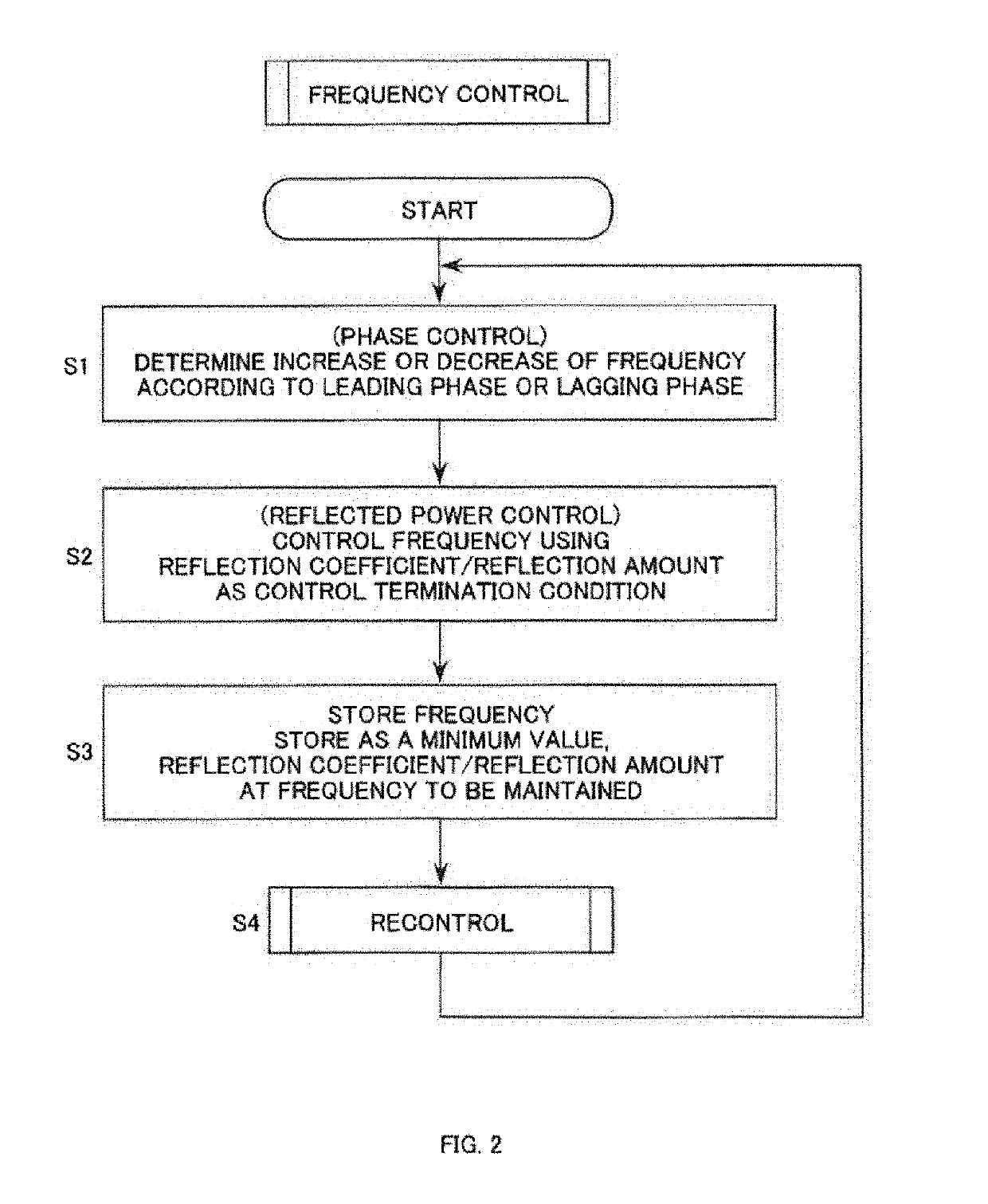
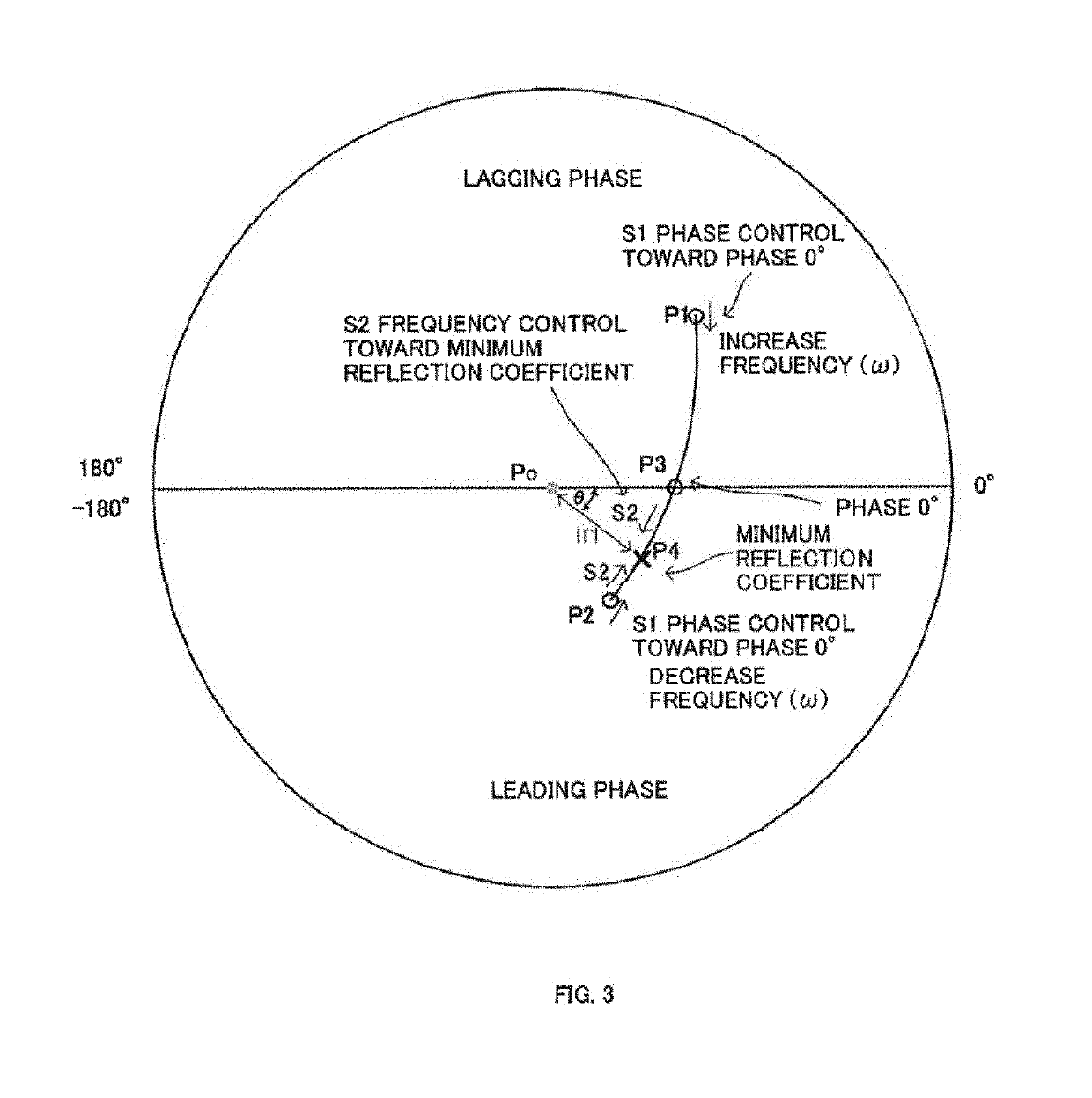
[0077]Hereinafter, with reference to FIGS. 1 to 3, frequency control of the RF power supply device of the present invention will be described, with reference to FIG. 4, a configuration of the RF power supply device will be described, and with reference to FIGS. 5 to 9 and FIGS. 10 to 17, a method of controlling the RF power supply device will be described. FIGS. 10 to 17 illustrate recontrol according to the RF power supply device of the present invention. With reference to FIGS. 18 and 19, there will be described a method of compensation for a phase difference due to a cable that is installed between the RF power supply device and a load according to the present invention.

[0078](Overview of the Frequency Control in the RF Power Supply Device According to the Present Invention)

[0079]With reference to a sch...


PUM


Abstract

In frequency control where impedance matching is performed by frequency sweep in an RF power supply device, a frequency sweep direction is specified, allowing a reflection coefficient and / or reflected power to move to a minimum, whereby it is possible to reduce a time length required until detecting the frequency that enables the reflection coefficient and / or the reflected power to be minimized. The frequency control for impedance matching in the RF power supply device is performed according to the following two-stage control; A) phase control that specifies the frequency sweep direction that allows the reflection coefficient and / or the reflected power to move to a minimum, based on the phase state of oscillating frequency, and that starts increasing or decreasing the frequency in thus specified sweep direction; and B) reflected power control where the reflection coefficient or the reflection amount is used as a control end condition for completing the frequency control.

Description

TECHNICAL FIELD[0001]The present invention relates to a high-frequency power supply device (an RF power supply device) and to a method of controlling the RF power supply device, and more particularly, it relates to an RF power supply device for supplying power to a load such as a plasma processor intended for use involving electrical discharge; for example, plasma etching and plasma CVD, and to a method of controlling the RF power supply device.BACKGROUND ART[0002]Variation in the state of electrical discharge of the load may cause fluctuation of impedance. For example, the impedance may fluctuate between before starting discharge and after starting discharge in the plasma load. Also in the course of discharging, the impedance may vary due to the state of gas supplied to the plasma, creations within a plasma chamber, or environmental changes.[0003]It is known that impedance matching is performed by adjusting a matching circuit that is provided between the RF power supply device and ...

Claims


Application Information

Patent Timeline
Patent Type & Authority Patents(United States)
IPC IPC(8): H01J37/32H03H7/38H03H7/40H05H1/46
CPCH01J37/32266H03H7/40H01J37/32183H05H2001/4682H01L21/3065H03H7/30H05H1/46H01J37/32174H01J37/32155H05H2242/20
Inventor YUZURIHARA, ITSUOOHMA, RYOSUKE
Owner KYOSAN ELECTRIC MFG CO LTD
Learn More