Variable performance axial flow ducted fan with high efficiency and reduced current drawn

a ducted fan, high efficiency technology, applied in the direction of magnetic circuit rotating parts, magnetic circuit shape/form/construction, liquid fuel engines, etc., can solve the problems of reducing fan efficiency, turbulence and inefficiencies at the rotor tips of airflow across conventional ductless axial flow fans, and putting a high demand on electric current and attending costs, so as to reduce torque, reduce drag, and reduce current drawn

Active Publication Date: 2019-11-12
NEWTON STEPHEN THOMAS +1
View PDF12 Cites 8 Cited by
  • Summary
  • Abstract
  • Description
  • Claims
  • Application Information

AI Technical Summary

Benefits of technology

The patent describes a fan design that can replace multiple types of fans currently on the market. It uses less electric current to produce the required flow, reducing operational costs. The fan also has an advantage in that it can be used in solar collection systems, which can extend the life of battery charging. Additionally, the design reduces the weight of rotating fans used in flying machines, allowing for longer flying times. The fan uses less magnetic force to rotate, as the force is applied at a point farther from the blades. This results in less torque needed to rotate the fan, even while maintaining the same flow and pressure requirements.

Problems solved by technology

The continuous nature of most production fan operations puts a high demand on electric current and the attending cost thereof.
Airflow across conventional ductless axial flow fans tends to generate turbulence and inefficiencies at the rotor tips.
While increased tolerances to reduce the cost of manufacture have the tradeoff of air turbulence that reduces fan efficiency and increases the noise generated during fan operation.
They also require high total pressures due to the resistance generated by the airflow through the duct network.
However, the motor size, air flow efficiency, noise generated by the fan, and related factors continue to be problematic in the industry.
Power consumption is a big cost element in all types of production.
The bell shaped duct inlet acting as an airfoil applied enough lift that it did not permit directional control or forward speed as desired.
With a rotor blade being pulled by magnets in its blade tips, the coning described would tend to pull the blade tip up, in and thus away from the stator and could in this way disrupt the electromagnetic energy rotating the blade discs.

Method used


Image

  • Variable performance axial flow ducted fan with high efficiency and reduced current drawn
  • Variable performance axial flow ducted fan with high efficiency and reduced current drawn
  • Variable performance axial flow ducted fan with high efficiency and reduced current drawn

Examples


Embodiment Construction

[0048]Integrated Fan Rotor Assembly

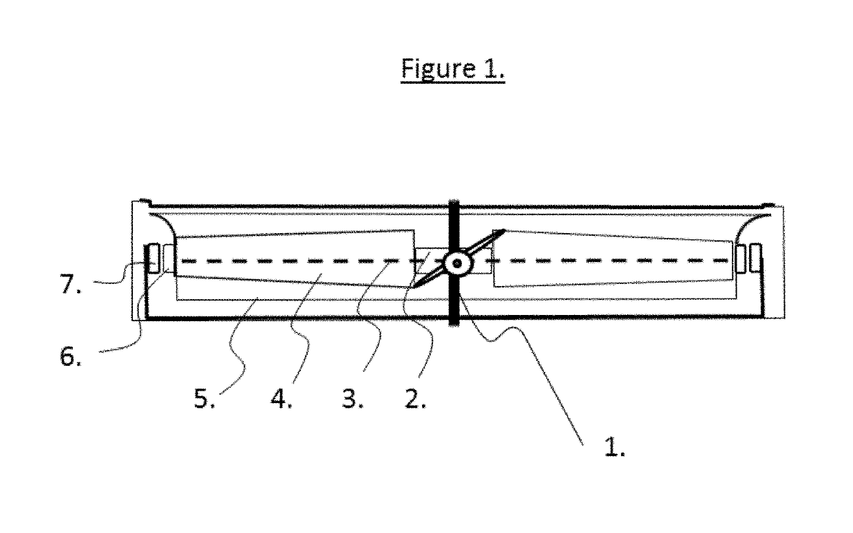
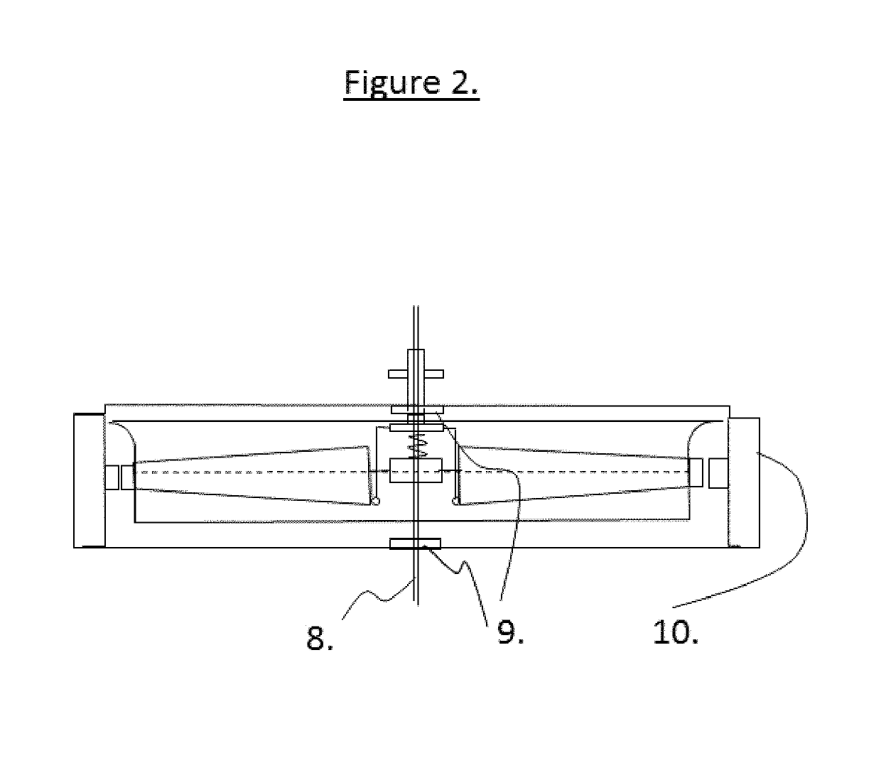
[0049]Referring to FIGS. 1 and 2, through a center line drawn from the air inlet through the air outlet is a main axle 1 and 8. This axle is retained in that position by sufficient support as determined by the designer. This support can be a front and rear bearing 9 if the fan is mounted vertically or top and bottom bearing 9.

[0050]The main axle 1 and 8 needs to be stiff enough to resist unbalanced rotational forces applied during continuous operation. If the environment in which the fan operates is subject to foreign object damage the designer will have to balance increased structure to account for such risk against the safety issues involved, cost of manufacture, and cost of operation.

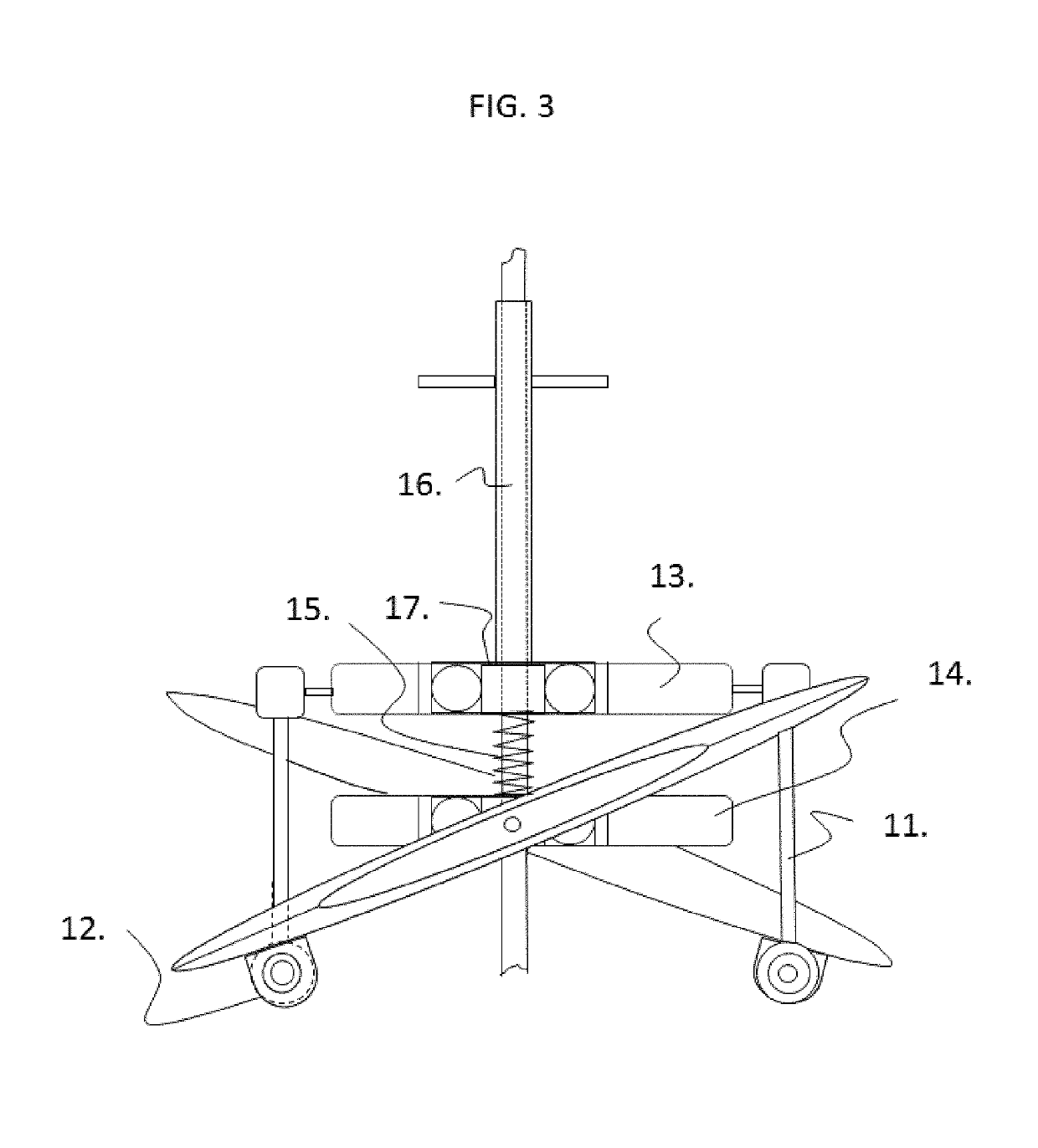
[0051]Fixed linearly on the main axle 1 and 8 and located at the center point of the stator assembly 7, is a fan blade axle mounting hub 2 and 14 (FIG. 3). This hub is so named as the axles on which the fan blades 4 and 22 are mounted are themselves mounted on this ...


PUM


Abstract

The ideal design for a fan with variable performance that can replace a family of current axial flow ducted, un-ducted, and centrifugal fan designs by meeting air flow and pressure requirements while drawing less electric current to rotate and thus produce the required flow not only would reduce cost of operation over the life of the fan but opens new possibilities for direct connection to solar collection systems by greatly extending the life of the battery charge employed by the designer of the collection system. In addition the entry of flying machines using pairs of lifting fans such as hover bikes and quadcopters, manned or unmanned is driving a need to re-examine the application of force applied to rotate these fans to achieve a reduction in aircraft weight and increase flying time for a given battery charge or load of fuel.

Description

CROSS REFERENCE TO RELATED APPLICATIONS[0001]This application claims priority from U.S. Provisional Application Ser. No. 62 / 427,292 filed Nov. 29, 2016.STATEMENT REGARDING FEDERALLY SPONSORED RESEARCH OR DEVELOPMENT[0002]This invention was not made with U.S. Government support.BACKGROUND PRIOR ART1. Technical Field[0003]The present invention relates generally to ducted axial flow fans and, in particular, to high efficiency fans having reduced power consumption.2. Description of Related Art[0004]Ducted axial flow fans are axial flow fans mounted within a cylindrical shroud or duct. The duct reduces losses in thrust from the tips of the propellers, reduces noise and varying the fan blade angle of attack allows the designer to advantageously affect the velocity and pressure of the airflow.[0005]An axial fan is a type of a compressor that increases the pressure of the air flowing through it. The blades of the axial flow fan force air to move parallel to the shaft about which the blades ...

Claims


Application Information

Patent Timeline
IPC IPC(8): F04D25/06F04D29/40H02K1/24H02K7/14H02K21/24F04D29/32F04D29/36H02K1/17B64C11/00
CPCH02K1/17F04D25/0606F04D29/403H02K7/14H02K1/24H02K21/24F04D29/326F04D29/362B64C11/001F04D25/066H02K23/04B60V1/14B64D27/24Y02T50/60Y02T50/40B64U50/14B64U50/19B64U30/26
Inventor NEWTON, STEPHEN THOMASNEWTON, II, STEPHEN THOMAS
Owner NEWTON STEPHEN THOMAS
Why Eureka
Try Eureka