
Numerical controller for controlling tapping

a controller and number technology, applied in the field of numerical controllers, can solve the problems of increasing the synchronization error between the spindle and the drilling axis, increasing the delay of the operation of the spindle with respect to the command, and difficulty in ensuring the synchronization accuracy, so as to maintain the machining accuracy of the rigid tap and shorten the cycle time

Active Publication Date: 2019-10-29
FANUC LTD
View PDF32 Cites 0 Cited by
  • Summary
  • Abstract
  • Description
  • Claims
  • Application Information

AI Technical Summary

Benefits of technology

This approach enables the reduction of cycle time while maintaining machining accuracy by absorbing positional deviations and setting appropriate error thresholds, allowing for precise synchronization error monitoring without the need for unnecessary spindle stops.

Problems solved by technology

This is because a certain degree of delay occurs from a command from the numerical controller to an actual operation of a spindle (movement in a Z direction and spindle rotation), and it is difficult to secure the synchronization accuracy if the feedrate is too fast.
When the spindle stop at the point R is not executed, the following problems may occur.
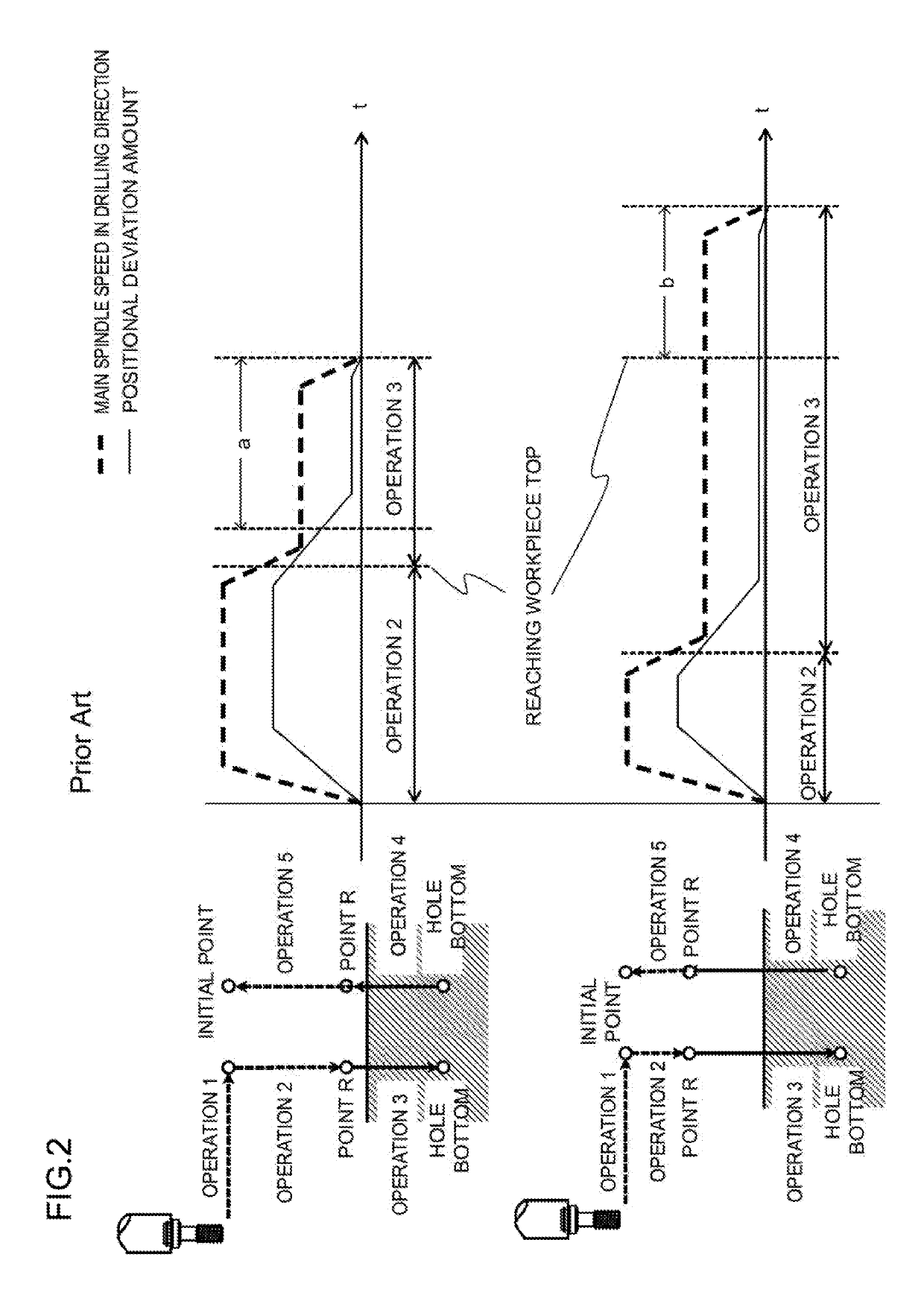
First, a positional deviation amount of a drilling axis at the point R, that is, the delay of the operation of the spindle with respect to the command increases, and a synchronizing error of a rigid tap, that is, the synchronizing error between the spindle and the drilling axis also increases.
As a result, there is a possibility that the machining accuracy may become worse than that in the case of executing the spindle stop at the point R. That is, if the error caused by not executing the spindle stop at the point R is overlooked, there occurs a disadvantage of missing an error which should not be overlooked.
If the numerical controller grasps a position of a top of a workpiece, there is a possibility that it is possible to maintain the machining accuracy by performing strict synchronization accuracy monitoring from the workpiece top at the latest in the case of not executing the spindle stop at the point R. However, such a method has not been proposed to date.
Alternatively, if a distance between the point R and the workpiece top is increased, it is possible to absorb the positional deviation amount of the drilling axis while a tool is moved from the point R to the workpiece top, and thus, there is a possibility that the machining accuracy of the tap can be maintained to some extent without stopping the spindle at the point R. However, there is a problem that the cycle time increases if the distance between the point R and the workpiece top is increased.
In this case, the cycle time can be shortened, but the error amount at the start of cutting increases.

Method used


Image

  • Numerical controller for controlling tapping
  • Numerical controller for controlling tapping
  • Numerical controller for controlling tapping

Examples


first embodiment

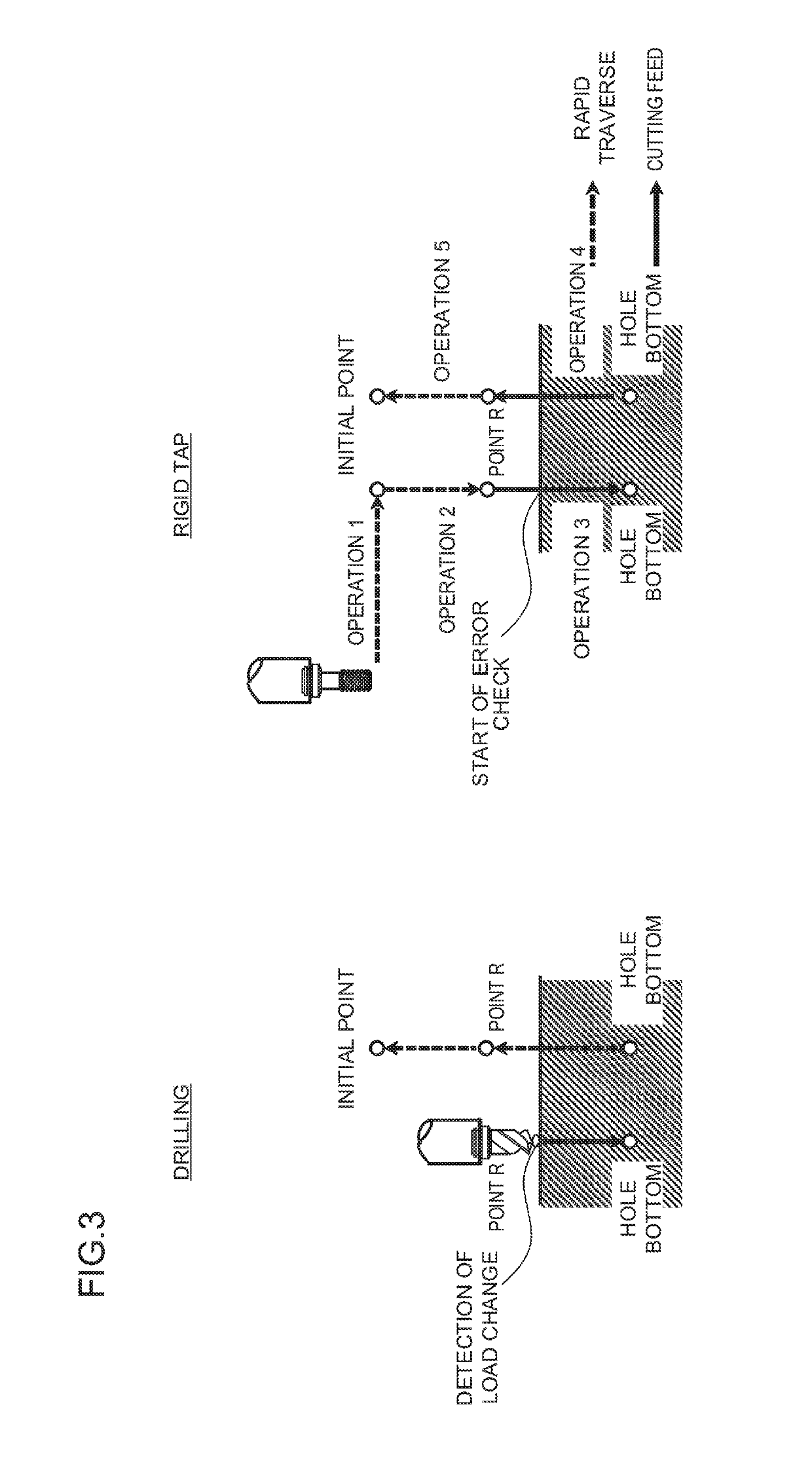
[0030]A numerical controller 100 according to a first embodiment is characterized by starting synchronization error monitoring from a workpiece top instead of the point R.

[0031]FIG. 7 is a block diagram illustrating a configuration of the numerical controller 100 according to the first embodiment of the present invention. The numerical controller 100 includes a rigid tap control unit 110, a synchronization error monitoring unit 120, and a workpiece top detection unit 130. The numerical controller 100 is typically an information processing apparatus that includes a central processing unit (CPU), a storage device, and an input / output device, and logically implement the rigid tap control unit 110, the synchronization error monitoring unit 120, and the workpiece top detection unit 130 by causing the CPU to execute a predetermined program.

[0032]The rigid tap control unit 110 controls a spindle to execute a rigid tap. The synchronization error monitoring unit 120 monitors a synchronizatio...

second embodiment

[0041]A numerical controller 100 according to a second embodiment is characterized by including a mechanism to automatically adjust a position of a point R.

[0042]FIG. 8 is a block diagram illustrating a configuration of the numerical controller 100 according to the second embodiment of the present invention. The numerical controller 100 includes a rigid tap control unit 110, a synchronization error monitoring unit 120, a workpiece top detection unit 130, and a machine learning unit 140. The numerical controller 100 is typically an information processing apparatus that includes a central processing unit (CPU), a storage device, and an input / output device, and logically implement the rigid tap control unit 110, the synchronization error monitoring unit 120, the workpiece top detection unit 130, and the machine learning unit 140 by causing the CPU to execute a predetermined program.

[0043]The rigid tap control unit 110 controls a spindle to execute a rigid tap. The synchronization error...

embodiment

2. Embodiment

[0079]FIG. 5 is a view illustrating a concept of machine learning for optimization of the point R in the machine learning unit 140. Incidentally, FIG. 5 only illustrates the configuration necessary for description of machine learning according to the present embodiment.

[0080]The machine learning unit 140 includes a state observation unit 141, a determination data acquisition unit 142, a learning unit 143, and a decision-making unit 144. The learning unit 143 includes a reward calculation unit 1431 and a value function update unit 1432.

[0081]The state observation unit 141 acquires the state data as information to specify the environment (the state st described in ). In the present embodiment, the spindle feedrate, the spindle rotational speed, and the workpiece top position are used as the state data. The spindle feedrate and the spindle rotational speed are data that the numerical controller 100 can acquire from the machining device. The workpiece top position can be ob...


PUM

PropertyMeasurementUnit
rotational speedaaaaaaaaaa
feed rateaaaaaaaaaa
heightaaaaaaaaaa

Abstract

Provided is a numerical controller capable of shortening cycle time while maintaining machining accuracy of a rigid tap. The numerical controller includes: a rigid tap control unit that executes a rigid tap by synchronizing rotational speed of a spindle with feedrate; a synchronization error monitoring unit that starts or terminates monitoring of a synchronization error between the rotational speed of the spindle and the feedrate at a point R set to a height equal to or higher than a top of a workpiece; and a workpiece top detection unit that detects a position of the workpiece top. The synchronization error monitoring unit starts monitoring the synchronization error at the position of the workpiece top instead of the point R.

Description

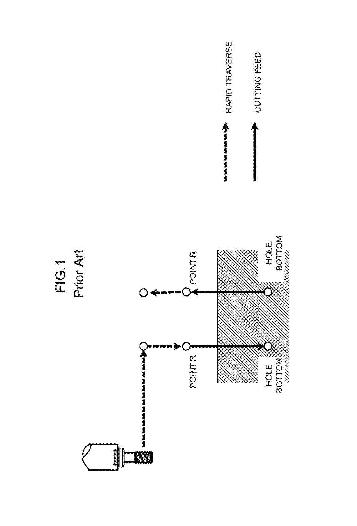
CROSS-REFERENCE TO RELATED APPLICATIONS[0001]This application is a new U.S. Patent Application that claims benefit of Japanese Application No. 2016-226254, filed Nov. 21, 2016, the disclosure of this application is being incorporated herein by reference in its entirety for all purposes.BACKGROUND OF THE INVENTION1. Field of the Invention[0002]The present invention relates to a numerical controller, and more particularly to a numerical controller capable of shortening cycle time of a rigid tap.2. Description of the Related Art[0003]The rigid tap is a processing method in which threading is performed at a constant pitch by synchronizing rotational speed of a spindle with feedrate. For example, Japanese Patent No. 3433967 discloses an example of a rigid tap of the related art.[0004]With reference to FIG. 1, the rigid tap of the related art will be described. A position at which the synchronization between the rotational speed of the spindle and the federate is started is referred to as...

Claims


Application Information

Patent Timeline
Patent Type & Authority Patents(United States)
IPC IPC(8): G05B19/402
CPCG05B19/402G05B2219/31455B23G11/00G05B19/186G05B2219/45216
Inventor WATANABE, TOORUKUBOTA, TOORU
Owner FANUC LTD
Learn More