Valve and manufacturing method for valve

Active Publication Date: 2019-10-29
SEIKO EPSON CORP
View PDF16 Cites 1 Cited by
  • Summary
  • Abstract
  • Description
  • Claims
  • Application Information

AI Technical Summary

Benefits of technology

The patent text describes a structure that prevents a defect in a valve mechanism caused by a fixing member blocking the opening, which could prevent the valve from operating normally. This is achieved by making the flow path resistance between the components gradually decrease from the opening side to the third surface side, which encourages the fixing member to flow to the third surface side and prevents it from blocking the opening.

Problems solved by technology

However, in the valve unit described in JP-A-2016-022704, for example, a structure in which the supporting member and the abutting member are stacked is not appropriately formed due to deformation and a positional shift, a portion where the supporting member and the abutting member are stacked interferes the valve body, and thereby the valve body might not operate normally.

Method used


Image

  • Valve and manufacturing method for valve
  • Valve and manufacturing method for valve
  • Valve and manufacturing method for valve

Examples


embodiment 1

Outline of Printer

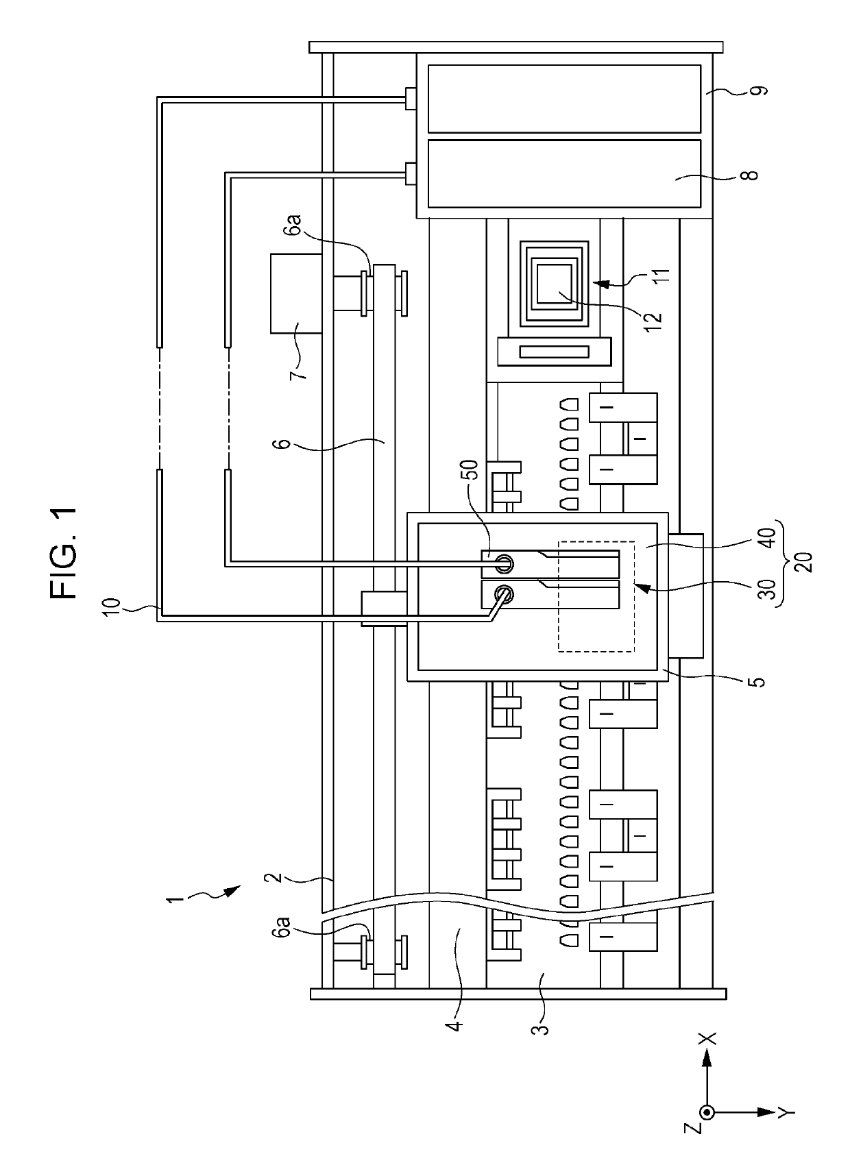
[0089]FIG. 1 is a schematic plan view of an ink jet recording apparatus (hereinafter, referred to as a printer).

[0090]As illustrated in FIG. 1, a printer 1 includes a substantially rectangular main body frame 2. Inside the main body frame 2, a medium supporting member 3 that supports a recording medium (not illustrated) runs in a longitudinal direction of the main body frame 2 (a main scanning direction). On the medium supporting member 3, a recording medium, such as paper, is fed by a paper feeding mechanism (not illustrated) in a lateral direction of the main body frame 2 (a sub-scanning direction). In addition, a rod-like guide shaft 4 that extends in the main scanning direction is provided above the medium supporting member 3 inside the main body frame 2.

[0091]In the following description, the main scanning direction will be referred to as an X-direction, the sub-scanning direction will be referred to as a Y-direction, and a thickness direction of the printer 1...

embodiment 2

[0208]FIG. 11 is a view corresponding to FIG. 4, and is a schematic view illustrating the outline of a valve unit according to Embodiment 2. FIG. 12 is a view corresponding to FIG. 11, and is a schematic view illustrating the outline of another valve unit according to Embodiment 2.

[0209]A main difference of a valve unit 50A according to the embodiment from the valve unit 50 according to Embodiment 1 is that a recessed portion 91 is formed in a valve seat 600 and the inclined portion 45, the first inclined surface 72A, and the second inclined surface 72C are not formed in the valve seat 600.

[0210]Hereinafter, the valve unit 50A according to the embodiment will be described with reference to FIG. 11, focusing on differences from Embodiment 1. In addition, configuration parts which are the same as those of Embodiment 1 will be assigned with the same reference signs, and overlapping description will be omitted. The valve unit 50A is also an example of a “valve mechanism”.

[0211]As illust...

embodiment 3

[0239]FIG. 15 is a schematic view illustrating an open state of an open / closed valve according to Embodiment 3. FIG. 16 is a schematic view illustrating a closed state of the open / closed valve according to the embodiment.

[0240]The printer 1 according to Embodiment 1 has a valve mechanism that opens / closes the flow path of an ink between the ink tanks 8 and the recording head 20 (the valve unit 50). The valve mechanism (the valve unit 50) is a mechanism for appropriately supplying an ink to the recording head 20, and is an open / closed valve that is opened to supply an ink to the recording head 20 when an ink is ejected from the recording head 20 and an ink pressure inside the recording head 20 declines and that is closed when an ink is supplied to the recording head 20 and an ink pressure inside the recording head 20 rises.

[0241]A printer according to the embodiment has another valve mechanism (an open / closed valve 100) between the ink tanks 8 and the valve unit 50. Another valve mec...


PUM


Abstract

A valve includes a valve seat having a hole configured as a flow path, a valve body configured to open / close the flow path due to relative movement with respect to the valve seat, an opening member having a first surface fixed to one of the valve seat and the valve body, a second surface configured to separate away and abut the other one of the valve seat and the valve body, a third surface which intersects the first and second surfaces, and an opening penetrating the first and second surfaces, a fixing member that fixes the first surface to the one of the valve seat and the valve body, and an inclined portion, which makes an interval between the one of the valve seat and the valve body and the first surface long in a direction from the opening to the third surface.

Description

BACKGROUND1. Technical Field[0001]The present invention relates to a valve applicable to a recording apparatus that ejects an ink onto a recording medium to perform recording and a manufacturing method for the valve.2. Related Art[0002]For example, an ink jet recording apparatus that ejects a liquid (an ink) as droplets onto a recording medium to perform recording onto the recording medium is known. As such an ink jet recording apparatus, there is an apparatus in which an ink is supplied from a liquid storage, such as an ink tank, to a recording head via a supply pipe, such as a tube, and the ink supplied from the liquid storage is ejected as droplets from a nozzle opening of the recording head. In addition, an apparatus, in which a valve unit (a valve or a valve mechanism) that is a pressure regulating valve is provided in the middle of a flow path of an ink such that an ink supplied from liquid storage is supplied to a recording head at a predetermined pressure, is proposed (for e...

Claims


Application Information

Patent Timeline
IPC IPC(8): B41J2/175F16K1/12C09D5/00F16K7/12F16K27/02F16K27/10F16K99/00
CPCF16K99/0005B41J2/175F16K27/10F16K1/12B41J2/17509C09D5/00B41J2/17596F16K99/0057F16K27/02F16K7/12F16K2099/0092F16K2099/0073F16K1/32F16K1/36F16K31/122
Inventor ISHIDA, YUKIMASAOCHIAI, KENJIHANAGAMI, TAIKINOGUCHI, DAISUKEMATSUOKA, HIRONORI
Owner SEIKO EPSON CORP
Why Eureka
Try Eureka