
Light emitting device and plant cultivation method

a technology of light-emitting devices and plant cultivation methods, which is applied in the field of plant cultivation methods, can solve the problems of insufficient effect of plant growth promotion, and achieve the effect of promoting plant growth

Active Publication Date: 2019-10-29
NICHIA CORP
View PDF13 Cites 1 Cited by
  • Summary
  • Abstract
  • Description
  • Claims
  • Application Information

AI Technical Summary

Benefits of technology

[0015]According to embodiments of the present disclosure, a light emitting device capable of promoting growth of plants and a plant cultivation method can be provided.

Problems solved by technology

However, even though plants are merely irradiated with lights having different wavelengths as in the plant growth method disclosed in Japanese Unexamined Patent Publication No. 2009-125007, the effect of promoting plant growth is not sufficient.

Method used


Image

  • Light emitting device and plant cultivation method
  • Light emitting device and plant cultivation method
  • Light emitting device and plant cultivation method

Examples


examples

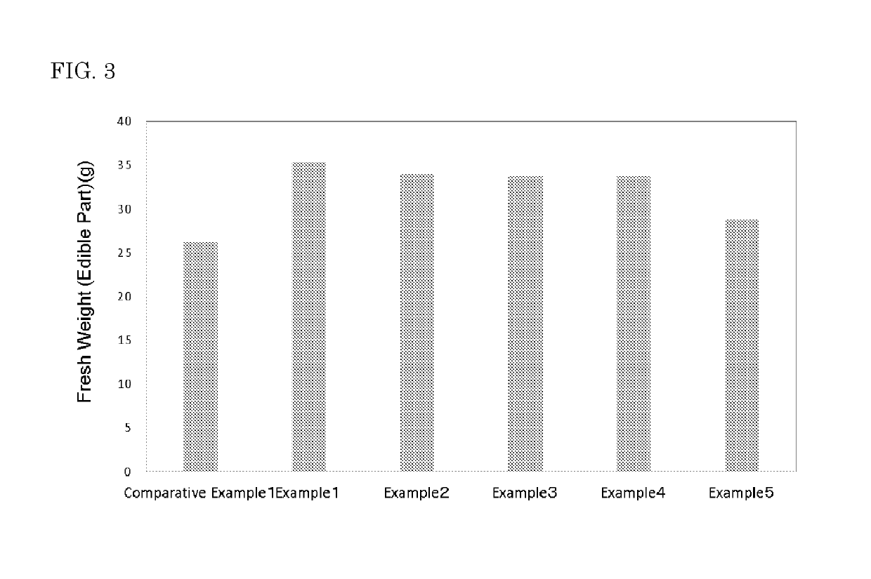
[0082]The present invention is further specifically described below by Examples and Comparative Examples.

examples 1 to 5

First Fluorescent Material

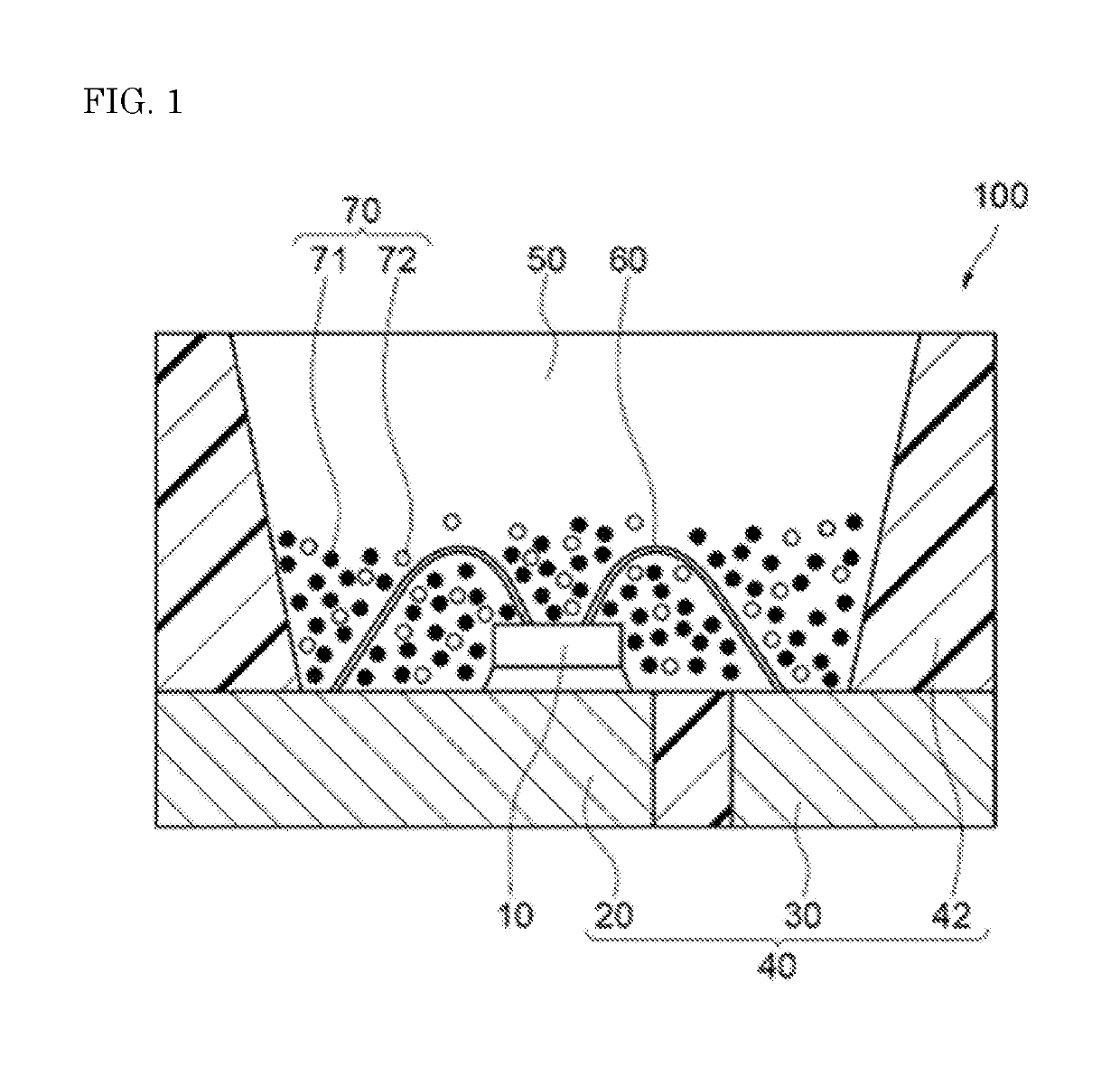
[0083]Two fluorescent materials of fluorogarmanate fluorescent material that is activated by Mn4+, having a light emission peak at 660 nm and fluorescent material containing silicon nitride that are activated by Eu2+, having a light emission peak at 660 nm were used as the first fluorescent material 71. In the first fluorescent material 71, a mass ratio of a MGF fluorescent material to a CASN fluorescent material (MGF:CASN) was 95:5.

Second Fluorescent Material

[0084]Fluorescent material that is obtained by the following production method was used as the second fluorescent material 72.

[0085]55.73 g of Y2O3 (Y2O3 content: 100 mass %), 0.78 g of CeO2 (CeO2 content: 100 mass %), 0.54 g of Cr2O3 (Cr2O3 content: 100 mass %,) and 42.95 g of Al2O3 (Al2O3 content: 100 mass %) were weighed as raw materials, and 5.00 g of BaF2 as a flux was added to the mixture. The resulting raw materials were dry mixed for 1 hour by a ball mill. Thus, a raw material mixture was obtai...


PUM


Abstract

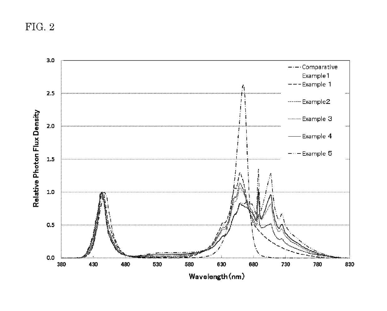
Provided is a light emitting device that includes a light emitting element having a light emission peak wavelength ranging from 380 nm to 490 nm, and a fluorescent material excited by light from the light emitting element and emitting light having at a light emission peak wavelength ranging from 580 nm or more to less than 680 nm. The light emitting device emits light having a ratio R / B of a photon flux density R to a photon flux density B ranging from 2.0 to 4.0 and a ratio R / FR of the photon flux density R to a photon flux density FR ranging from 0.7 to 13.0, the photon flux density R being in a wavelength range of 620 nm or more and less than 700 nm, the photon flux density B being in a wavelength range of 380 nm or more and 490 nm or less, and the photon flux density FR being in a wavelength range of 700 nm or more and 780 nm or less.

Description

CROSS-REFERENCE TO RELATED APPLICATION[0001]The application claims benefit of Japanese Patent Application No. 2016-128835 filed on Jun. 29, 2016, the entire disclosure of which is hereby incorporated by reference in its entirety.BACKGROUND[0002]Technical Field[0003]The present disclosure relates to a light emitting device and a plant cultivation method.[0004]Description of Related Art[0005]With environmental changes due to climate change and other artificial disruptions, plant factories are expected to increase production efficiency of vegetables and be capable of adjusting production in order to make it possible to stably supply vegetables. Plant factories that are capable of artificial management can stably supply clean and safe vegetables to markets, and therefore are expected to be the next-generation industries.[0006]Plant factories that are completely isolated from external environment make it possible to artificially control and collect various data such as growth method, gro...

Claims


Application Information

Patent Timeline
Patent Type & Authority Patents(United States)
IPC IPC(8): A01G7/04A01G31/00H01L33/50A01G22/00
CPCH01L33/504A01G7/045A01G22/00A01G31/00H01L2224/48257H01L2224/48247Y02P60/149H01L2224/73265Y02P60/14A01G22/05A01G22/15A01G22/60C09K11/77348C09K11/664C09K11/7776
Inventor AMIYA, MIKAFUJIO, KAZUSHIGESUZUKI, TOMOKAZU
Owner NICHIA CORP
Learn More