
Security panel framing system and method

a security panel and frame technology, applied in the field of security window technology, can solve the problem of not intended summary, and achieve the effect of withstanding damage or attack, preventing damage, and preventing damage or attack

Active Publication Date: 2019-10-22
RIOT GLASS LLC
View PDF7 Cites 1 Cited by
  • Summary
  • Abstract
  • Description
  • Claims
  • Application Information

AI Technical Summary

Benefits of technology

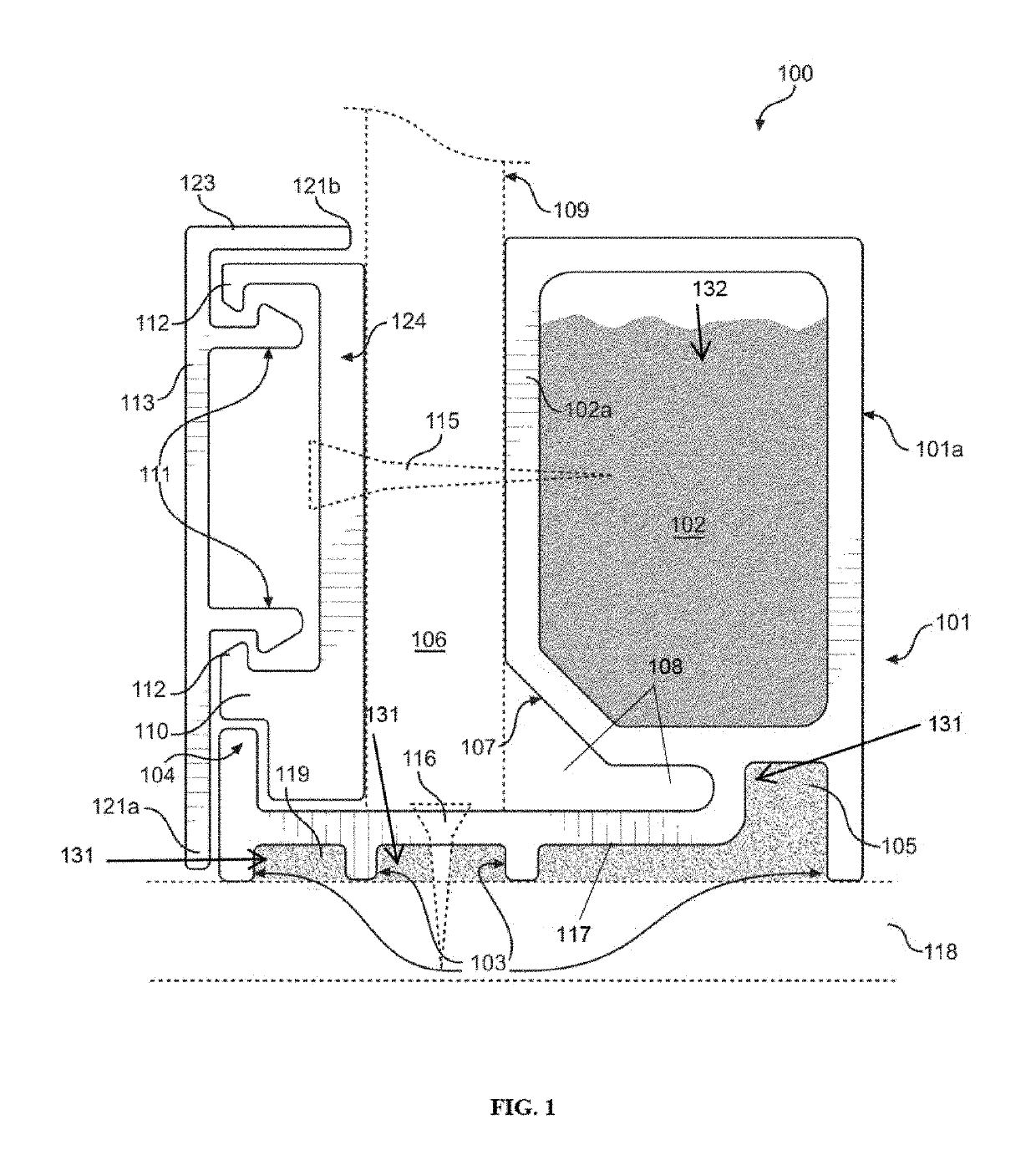
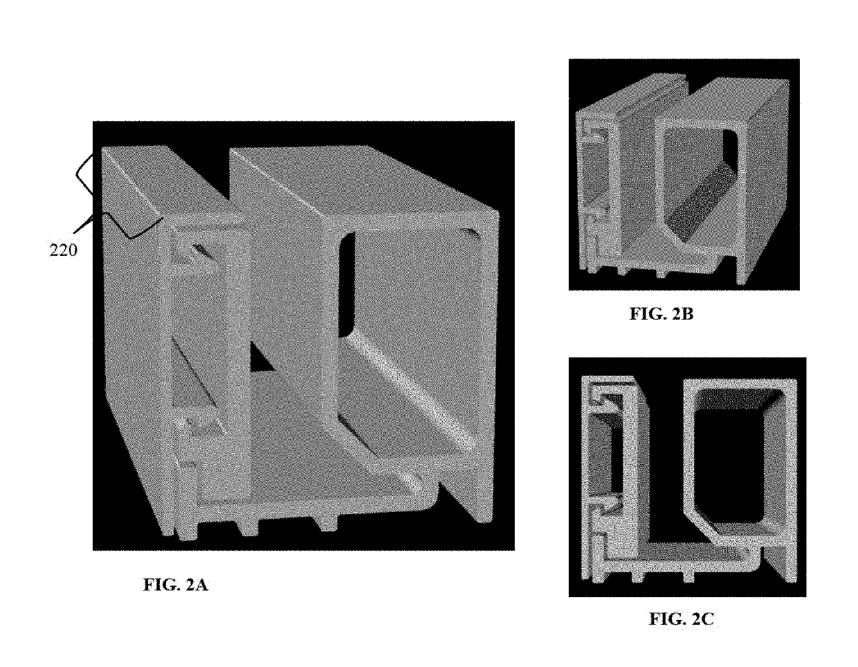
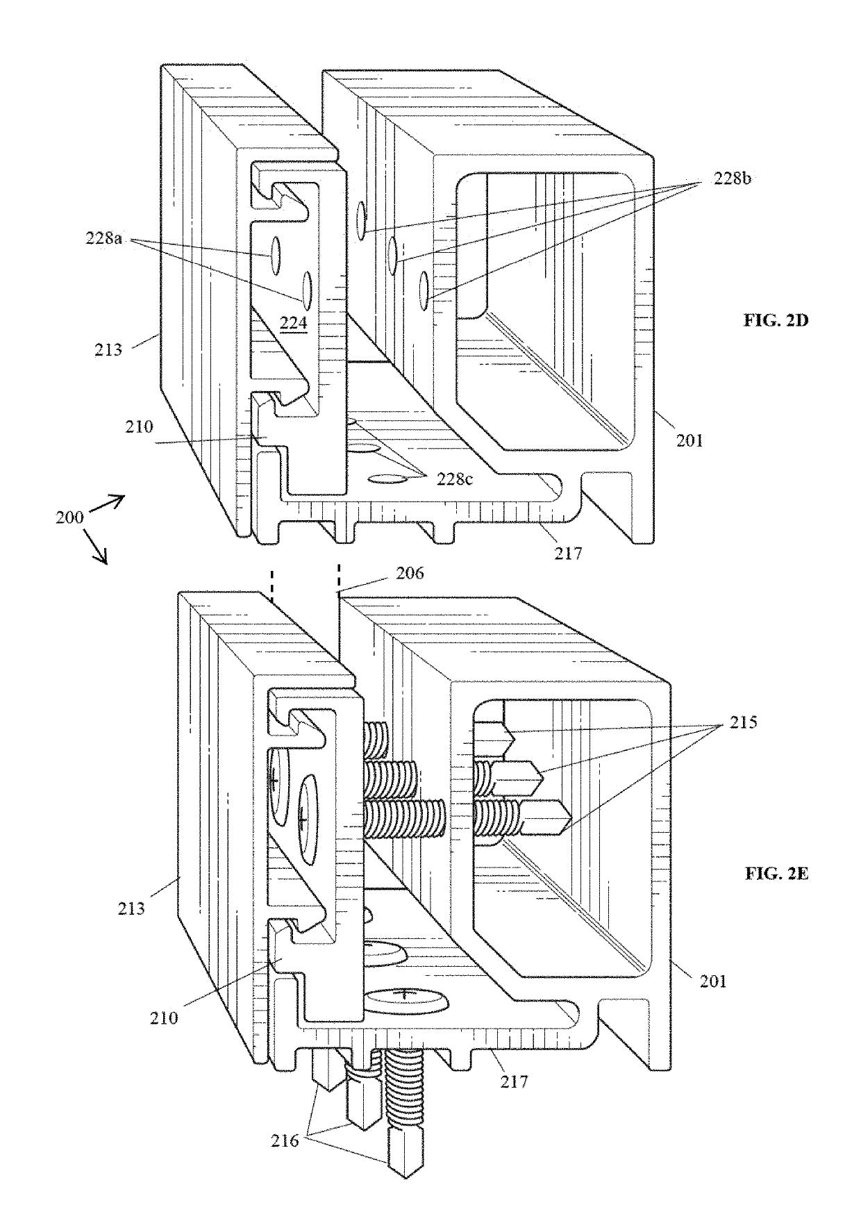
[0008]In an embodiment, a security panel framing system is provided, which includes a base, a wedge, and a cosmetic cap, all three elements fitting together to provide a secure, unique, cosmetically viable and pleasing appearance that blends seamlessly with existing commercial or residential glass framing. In some cases, the wedge and cap may be used without the base if the existing window frame has a component that serves the same purpose as the base, thereby eliminating the need for the base. In these cases, the wedge and cap are used as a stand-alone product.
[0009]In another aspect, a security panel framing system is provided, comprising: a base having: a base frame having a base frame front side, a base frame back side, a base frame top side, and a base frame bottom side; a base plate under the base frame bottom side and extending past the base frame front side, the base plate having a base plate front side, a base plate back side, a base plate top side, a base plate bottom side, and a stopper at the base plate front side; a plurality of legs along and extending downwards from the base plate bottom side, such that a plurality of spaces is formed between the legs, wherein a first leg of the plurality of legs is substantially aligned with the stopper, and wherein at least one space of the plurality of spaces is larger than the other spaces of the plurality of spaces; a hollow inner channel defined by the base frame front side, the base frame back side, the base frame top side, and the base frame bottom side; a wedge having: a wedge front side, a wedge back side, a wedge top side, and a wedge bottom side; an upper wedge lip at the wedge top side; a wedge wall extending between the wedge top side and the wedge bottom side; a reinforced end at the wedge bottom side; a lower wedge lip above the reinforced end; wherein the reinforced end and the bottom wedge lip are configured to fit around and be held in place by the stopper; and a cap configured to be associated with the wedge front side by having a plurality of prongs corresponding with the upper wedge lip and the lower wedge lip, wherein the cap covers a front end of the security panel framing system; an wherein the wedge is configured to sit at the base plate front side leaving a gap between the wedge back side and the base frame front side, the gap being configured to receive a portion of a security panel, such that the portion of the security panel is snugly encased by the base frame and the wedge. An advantage is that a protective security panel can be installed securely against a window or other glass panel and can be custom fit to any size window or glass panel. Another advantage may be that the security panel framing system is durable and can withstand damage or attack. Another advantage may be that the appearance of the security panel framing system is seamless and can blend into existing framing, and screw heads are hidden from view to provide a more aesthetically pleasing look. Another advantage may be that bugs, dust, water, or other contaminants may be blocked from entering the system or prevented from damaging the system by the sealant and desiccant.
[0010]In another aspect, a security panel framing system is provided, comprising: a wedge having: a wedge front side, a wedge back side, a wedge top side, and a wedge bottom side; a wedge wall extending between the wedge top side and the wedge bottom side; an upper wedge lip at the wedge top side; a reinforced end at the wedge bottom side; a lower wedge lip above the reinforced end; wherein the reinforced end and the bottom wedge lip are configured to fit around and be held in place by the stopper; and a cap configured to be associated with the wedge front side by having a plurality of prongs, wherein the cap covers a front end of the security panel framing system; and wherein the wedge back side is configured to align against a security panel, such that a portion of the security panel is snug against the wedge back side. Again, an advantage is that a protective security panel can be installed securely against a window or other glass panel and can be custom fit to any size window or glass panel, or an existing security panel can have securing means such as bolts or screws obscured from view by using the wedge and the cap. Another advantage may be that the security panel framing system is durable and can withstand damage or attack. Another advantage may be that the appearance of the security panel framing system is seamless and can blend into existing framing, and screw heads are hidden from view to provide a more aesthetically pleasing look.

Problems solved by technology

Moreover, this Summary is not intended for use as an aid in determining the scope of the claimed subject matter.

Method used


Image

  • Security panel framing system and method
  • Security panel framing system and method
  • Security panel framing system and method

Examples


Embodiment Construction

[0028]What follows is a description of various aspects, embodiments and / or examples in which the invention may be practiced. Reference will be made to the attached drawings, and the information included in the drawings is part of this detailed description. The aspects, embodiments and / or examples described herein are presented for exemplification purposes, and not for limitation purposes. It should be understood that structural and / or logical modifications could be made by someone of ordinary skills in the art without departing from the scope of the invention.

[0029]It should be understood that, for clarity of the drawings and of the specification, some or all details about some structural components or steps that are known in the art are not shown or described if they are not necessary for the invention to be understood by one of ordinary skills in the art.

[0030]For the following description, it can be assumed that most correspondingly labeled elements across the figures (e.g., 101 ...


PUM

PropertyMeasurementUnit
angleaaaaaaaaaa
lengthaaaaaaaaaa
forceaaaaaaaaaa

Abstract

A security panel framing system having a base frame; a base plate under a base frame bottom side, the base plate having a stopper; a hollow inner channel defined by the base frame; a wedge having a wedge top side, and a wedge bottom side; a wedge wall extending between the wedge top side and the wedge bottom side; a reinforced end at the wedge bottom side; wherein the reinforced end and a bottom wedge lip are configured to be held in place by the stopper; a cap configured to be associated with the wedge; and wherein the wedge is configured to sit at a base plate front side leaving a gap between the wedge back side and the base frame, the gap being configured to receive a security panel, such that the security panel is snugly encased by the base frame and the wedge.

Description

CROSS-REFERENCE TO RELATED APPLICATIONS[0001]This application claims the benefit of U.S. Provisional Application No. 62 / 468,882, filed Mar. 8, 2017, which is hereby incorporated by reference, to the extent that it is not conflicting with the present application.BACKGROUND OF INVENTION1. Field of the Invention[0002]The invention relates generally to security window technology and more particularly to a system and method for upgrading existing windows to withstand attacks and other types of damage.2. Description of the Related Art[0003]The typical window has a frame in which a glass panel is installed. The glass is typically easily breakable. Banks and other commercial establishments often need windows that can withstand an attack from an intruder or a bullet, for example. Some residents may also wish to upgrade their windows for security or safety purposes.[0004]The existing framing solutions that address this problem appear to be merely improvised assemblies of existing parts that a...

Claims


Application Information

Patent Timeline
Patent Type & Authority Patents(United States)
IPC IPC(8): E06B5/10E06B1/34E06B5/11E06B1/28E06B3/58E06B1/60E06B1/36
CPCE06B3/5828E06B1/366E06B5/116E06B1/6069E06B5/11E06B5/106E06B1/34E06B1/28
Inventor CAMPBELL, BRAD
Owner RIOT GLASS LLC
Learn More