
Femoral arterial cannula capable of guiding bidirectional perfusion flow

a cannula and femoral vein technology, applied in the field of cannulas, can solve the problems of distal limb perfusion, risk of leg necrosis, blood vessel breakage, etc., and achieve the effects of reducing the prevalence of ischemia in the distal limb, minimizing damage to the blood vessel, and being stably carried ou

Active Publication Date: 2019-10-22
SAMSUNG LIFE PUBLIC WELFARE FOUND
View PDF19 Cites 1 Cited by
  • Summary
  • Abstract
  • Description
  • Claims
  • Application Information

AI Technical Summary

Benefits of technology

The femoral arterial cannula described in this patent allows for better blood flow in the lower limb, reduces the risk of ischemia, and can be easily inserted without damaging blood vessels. The cannula has a mark to help guide its removal without harming the blood vessel. Overall, this device provides a more stable and reliable method for perfusing the lower limb.

Problems solved by technology

At this time, a cannula is inserted into the femoral artery in the vicinity of the groin region, and thus the biggest problem is distal limb perfusion.
Thus, while a femoral arterial cannula is maintained, blood is not supplied from the legs below the thigh to a distal portion, i.e., the feet, and, accordingly, there may be a risk for necrosis of the legs.
Thus, to prevent the occurrence of these problems, various techniques, such as separate antegrade catheterization, posterior tibial artery cannulation, and the like which supply blood to sides of the legs, are conventionally used, but all the techniques cause complications or breakage of blood vessels, and thus there are technical difficulties in applying these techniques.

Method used


Image

  • Femoral arterial cannula capable of guiding bidirectional perfusion flow
  • Femoral arterial cannula capable of guiding bidirectional perfusion flow
  • Femoral arterial cannula capable of guiding bidirectional perfusion flow

Examples


Embodiment Construction

Technical Problem

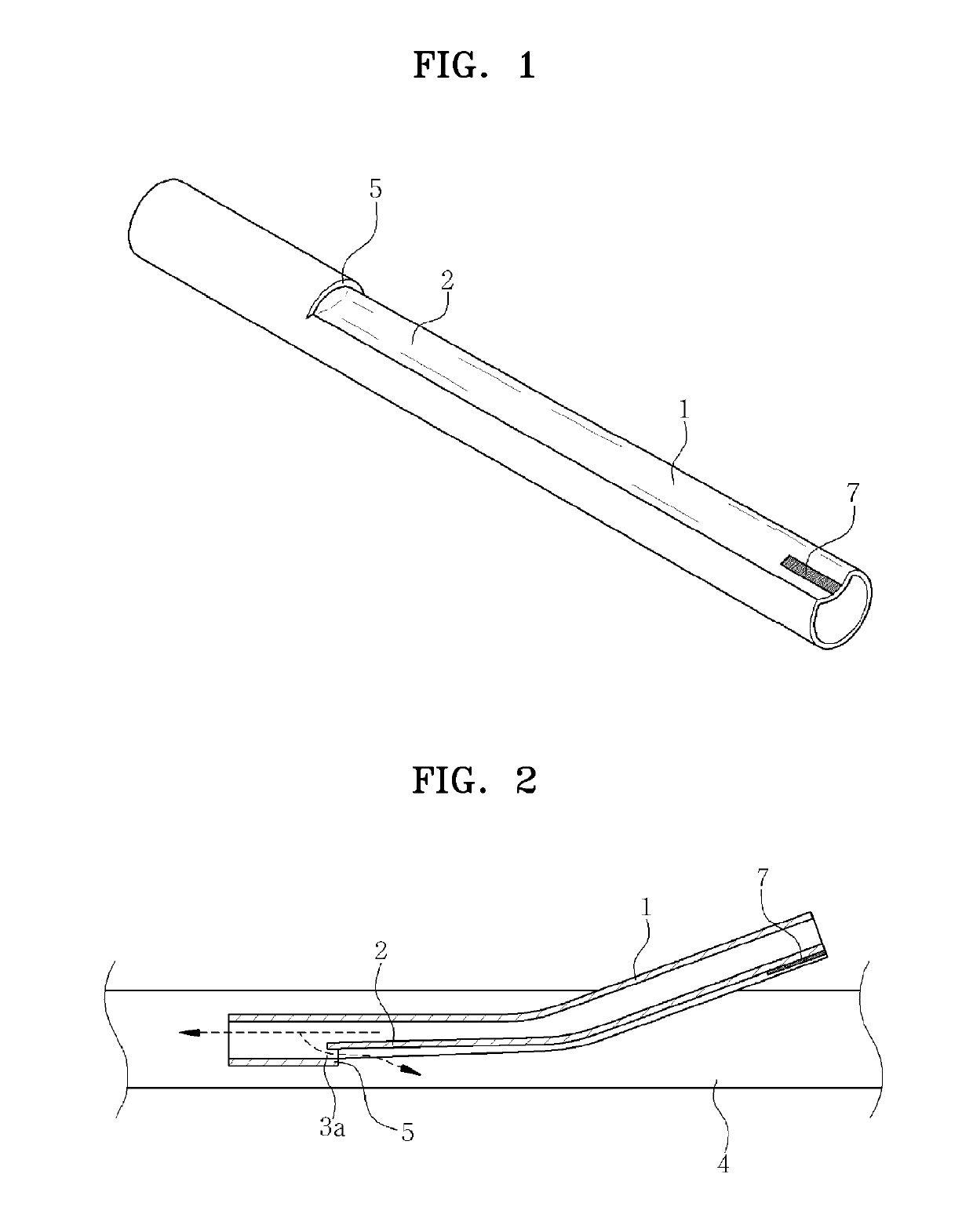
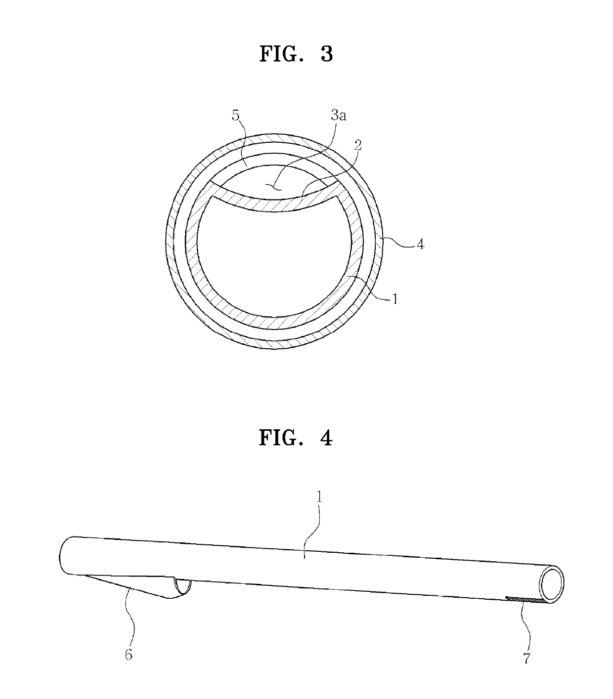
[0005]To address the problems described above, the present invention provides a femoral arterial cannula capable of guiding bidirectional perfusion that is provided, at an end thereof, with a perfusion guide channel or a through-hole together with the perfusion guide channel so that, during surgery, blood is supplied to the heart or the lung, and a part of the blood supplied to the heart or the lung inversely flows via the perfusion guide channel or the through-hole and the perfusion guide channel, thereby supplying blood even to the distal limb on the opposite side.

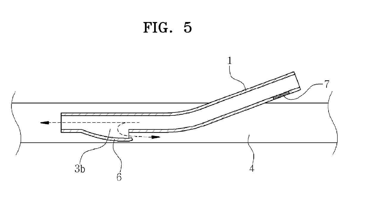
[0006]Another object of the present invention is to provide a femoral arterial cannula capable of guiding bidirectional perfusion, provided with a through-hole and a guide cover protruding therefrom to cover the though-hole at an end thereof so that a part of extracorporeally circulated blood inversely flows via the through-hole and the guide cover to thereby supply blood even to the distal limb on the o...


PUM


Abstract

The present invention relates to a cannula for femoral arterial bidirectional (a heart direction and a distal lower extremity direction) perfusion. The cannula, which has a cannula tube to be inserted into a blood vessel of the femoral artery, includes a perfusion guide channel formed as a concave part from a predetermined portion of an inner circumferential surface at an end of the cannula tube to the opposite end thereof in a length direction and further includes a through-hole provided at a boundary portion between the perfusion guide channel and the cannula tube in an end direction of the cannula tube, or includes a through-hole provided in a predetermined portion of an inner circumferential surface of an end of the cannula tube and a guide cover provided at an upper portion of the through-hole to cover the upper portion of the through-hole and guide perfusion. During surgery, perfusion proceeds towards the distal limb and thus blood may be stably supplied, and thus ischemia prevalence of the distal limb may be significantly reduced. Accordingly, the cannula can replace conventional techniques used for distal limb perfusion and may stably perform femoral arterial cannulation without technical difficulties such as complications or breakage of blood vessels.

Description

CROSS-REFERENCE TO RELATED APPLICATIONS[0001]This application is the National Stage entry under 35 U.S.C. § 371 of International Application Number PCT / KR2016 / 001772 filed on Feb. 24, 2016, published on Sep. 1, 2016 under publication number WO 2016 / 137212 A1, which claims the benefit of priority under 35 U.S.C. § 119 of Korean patent application number 10-2015-0026099 filed Feb. 24, 2015.TECHNICAL FIELD[0002]The present invention relates to a cannula for guiding perfusion in a direction into which a femoral arterial cannula is inserted and in a direction opposite to the insertion direction, and more particularly, to a femoral arterial cannula capable of guiding bidirectional perfusion that is provided, at an inner circumferential surface of an end of a cannula tube of a cannula to be inserted into the femoral artery, with a perfusion guide channel or a through-hole together with the perfusion guide channel, or with a through-hole that is larger than the through-hole and a guide cove...

Claims


Application Information

Patent Timeline
Patent Type & Authority Patents(United States)
IPC IPC(8): A61M1/36A61M25/00A61M1/10
CPCA61M25/0043A61M25/007A61M25/0041A61M1/3659A61M1/1008A61M2025/0008A61M2025/0073A61M25/0023A61M60/857
Inventor CHO, YANG HYUN
Owner SAMSUNG LIFE PUBLIC WELFARE FOUND
Learn More