
Additive synthesis of interleaved switch mode power stages for minimal delay in set point tracking

a technology of interleaved switch mode and power stage, applied in the field of power conversion, can solve the problems of increasing the response time of the converter, adding delay between the setpoint and the switchmode power converter's tracking, and the large lc filter components are also slower to react to setpoint changes

Active Publication Date: 2019-10-15
ADVANCED ENERGY IND INC
View PDF32 Cites 27 Cited by
  • Summary
  • Abstract
  • Description
  • Claims
  • Application Information

AI Technical Summary

Benefits of technology

The present patent relates to a power supply system that includes a switch module with two buck converter portions that generate output currents that are magnetically coupled. The system also includes a control module that generates two sequences of pulses to the buck converters, which are interleaved in time. The system can be used in a plasma system and includes a dynamic setpoint waveform generator. The power supply circuit includes a plurality of interleaved, switchmode, power conversion stages with a common output. The interconnect topology can be achieved by series connectivity or parallel connectivity. The technical effects of the present patent are improved power supply control and efficiency.

Problems solved by technology

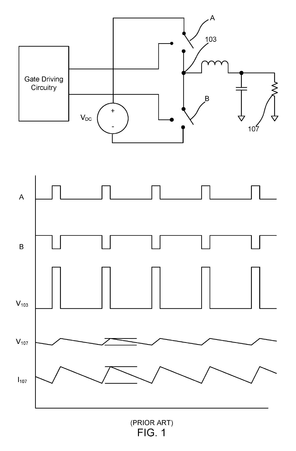
However, larger LC filter components are also slower to react to setpoint changes (i.e., they cause an increased response time of the converter).
Thus, as one reduces ripple with larger LC components, one also adds delay between the setpoint and switchmode power converter's tracking of the setpoint.
Higher voltages and currents also suggest the need for larger switches and larger LC components, thus further adding delay between the setpoint and the output's ability to rapidly track the setpoint.
Yet, power converters are limited to a maximum practical switching frequency due to switching losses, and thus the LC filter can only be reduced so far.
The problem is further exaggerated in high power applications since larger switches are needed, thus further limiting the maximum switching frequency and leading to larger LC filters.
These and other methods are known by those skilled in the art to reduce ripple and decrease response time, yet practical limits on switching speed, switch size, LC component size, and ripple lead to practical limits for various use cases.

Method used


Image

  • Additive synthesis of interleaved switch mode power stages for minimal delay in set point tracking
  • Additive synthesis of interleaved switch mode power stages for minimal delay in set point tracking
  • Additive synthesis of interleaved switch mode power stages for minimal delay in set point tracking

Examples


Embodiment Construction

[0046]The word “exemplary” is used herein to mean “serving as an example, instance, or illustration.” Any embodiment described herein as “exemplary” is not necessarily to be construed as preferred or advantageous over other embodiments.

[0047]Preliminary note: the flowcharts and block diagrams in the following Figures illustrate the architecture, functionality, and operation of possible implementations of systems, methods and computer program products according to various embodiments of the present invention. In this regard, some blocks in these flowcharts or block diagrams may represent a module, segment, or portion of code, which comprises one or more executable instructions for implementing the specified logical function(s). It should also be noted that, in some alternative implementations, the functions noted in the block may occur out of the order noted in the figures. For example, two blocks shown in succession may, in fact, be executed substantially concurrently, or the blocks...


PUM


Abstract

An apparatus utilizing additive interleaved switchmode (PWM) power conversion stages, having minimal or no output filter, to achieve high bandwidth or even ideally instantaneous power conversion. The additive process may involve voltage stacking of isolated PWM converters, which are interleaved in time, or may involve a single input power supply and inductively combining output currents of PWM power converters interleaved in time, with either additive circuit having minimal or no output filtering. This circuit may overcome limitations for the frequency of feedback control loops once thought to be physical limitations, such as, fundamental switching frequency, output filter delay and the Nyquist criteria.

Description

CLAIM OF PRIORITY UNDER 35 U.S.C. § 119[0001]The present Application for Patent claims priority to Provisional Application No. 62 / 767,421 entitled “ARBITRARY WAVEFORM POWER GENERATOR” filed Nov. 14, 2018, and assigned to the assignee hereof and hereby expressly incorporated by reference herein.FIELD OF THE DISCLOSURE[0002]The present disclosure relates generally to power conversion. In particular, but not by way of limitation, the present disclosure relates to systems, methods and apparatuses for arbitrary waveform power generation.DESCRIPTION OF RELATED ART[0003]Switching power converters, or switchmode power converters, using pairs of switches (e.g., metal-oxide semiconductor field-effect transistors (MOSFETS)) rose in popularity in the 1980s due to their efficiency in both up and down conversion of power. Switching power converters employ pulse-width modulated (PWM) control of switches along with LC filtering of a PWM output from the switches to generate an up or downconverted wa...

Claims


Application Information

Patent Timeline
Patent Type & Authority Patents(United States)
IPC IPC(8): H02M7/497H02M1/42H02M3/335
CPCH02M1/14H02M3/1584H02M1/15H02M1/4275H02M1/4291H02M3/1586H02M1/0043H02M7/49H05H2242/22H05H2242/20H02M3/158H02M7/497H02M1/08H02M1/4208H02M3/33507
Inventor PORTER, JR., ROBERT M.DORRENBACHER, JOHN
Owner ADVANCED ENERGY IND INC
Learn More