
Cyclotronic plasma actuator with arc-magnet for active flow control

a technology of active flow control and cyclotronic plasma, which is applied in the direction of digital transmission, air-flow influencers, transportation and packaging, etc., can solve the problems of insufficient control authority of existing methods and hinder the practical use of modern flow control techniques, and achieve the effect of reducing turbulent flow separation

Active Publication Date: 2019-10-15
CU AEROSPACE +1
View PDF8 Cites 7 Cited by
  • Summary
  • Abstract
  • Description
  • Claims
  • Application Information

AI Technical Summary

Problems solved by technology

However, practical use of modern flow control techniques has been hindered by high power requirements, integration challenges, and insufficient control authority of existing methods.

Method used


Image

  • Cyclotronic plasma actuator with arc-magnet for active flow control
  • Cyclotronic plasma actuator with arc-magnet for active flow control
  • Cyclotronic plasma actuator with arc-magnet for active flow control

Examples


Embodiment Construction

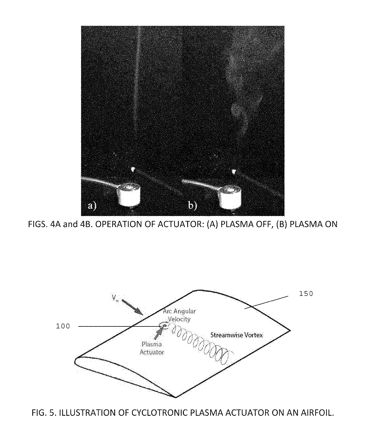
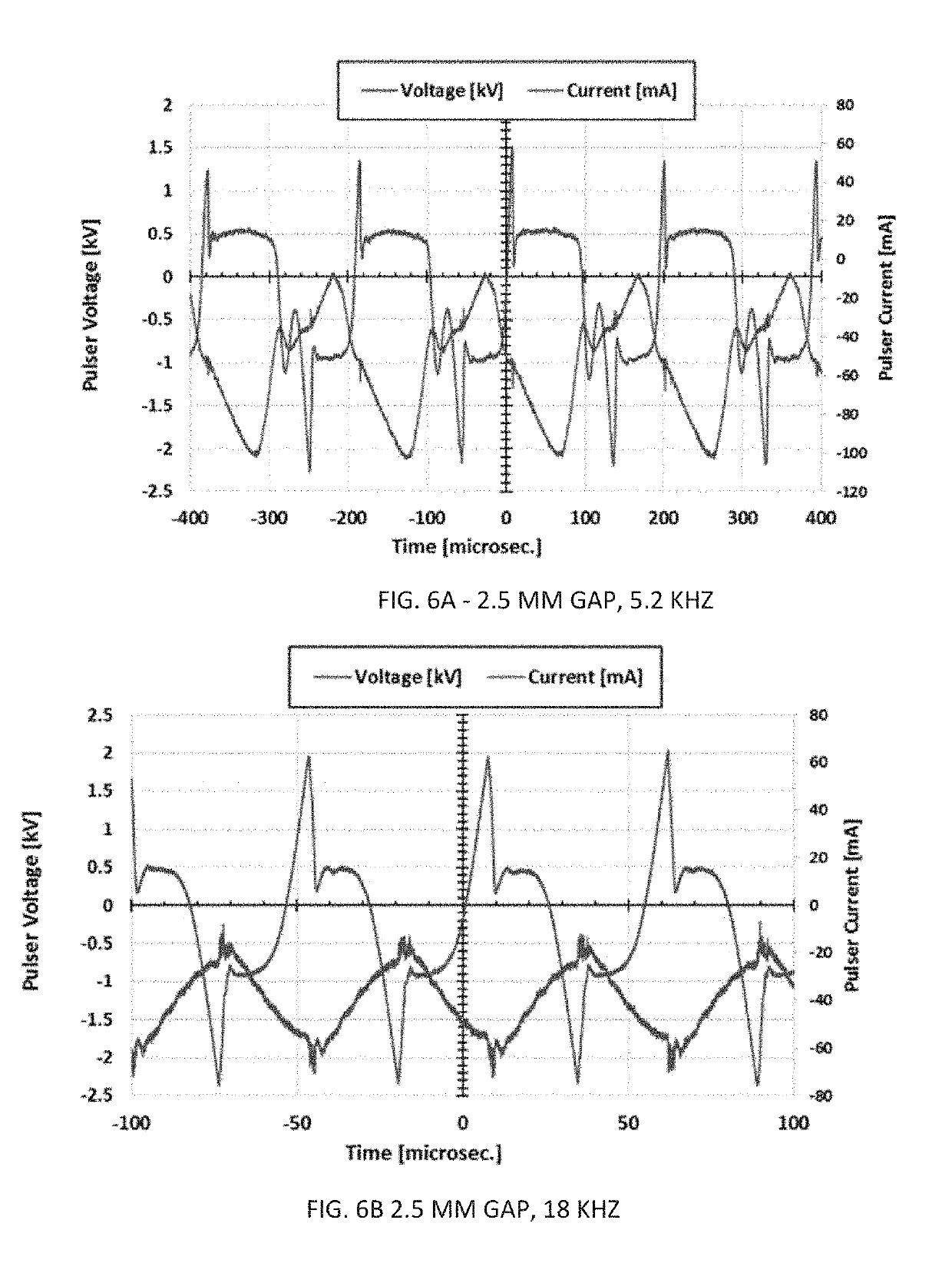
[0092]In order to provide an understanding of how the new actuation approach can be utilized in comparison to other actuation techniques, parametric studies were conducted to evaluate electrical characteristics and power requirements, measure magnetic field strengths, monitor device heating, and diagnose plasma arc behaviors with various control circuits. High-speed imaging enabled visualization of the sweeping AC arc, including the influence of electro-mechanical properties on the rotational velocity of the actuator arc. The impact of the device on the flow-field was evaluated using planar velocimetry techniques. Multiphysics simulation techniques were applied to develop a qualitative understanding of the physics related to the experimental observations, laying the groundwork for advanced modeling and simulation.

[0093]Nomenclature

[0094]AC=alternating current

[0095]B=magnetic field strength

[0096]CRT=cathode ray tube

[0097]DBD=dielectric barrier discharge

[0098]DC=direct current

[0099]fp...


PUM


Abstract

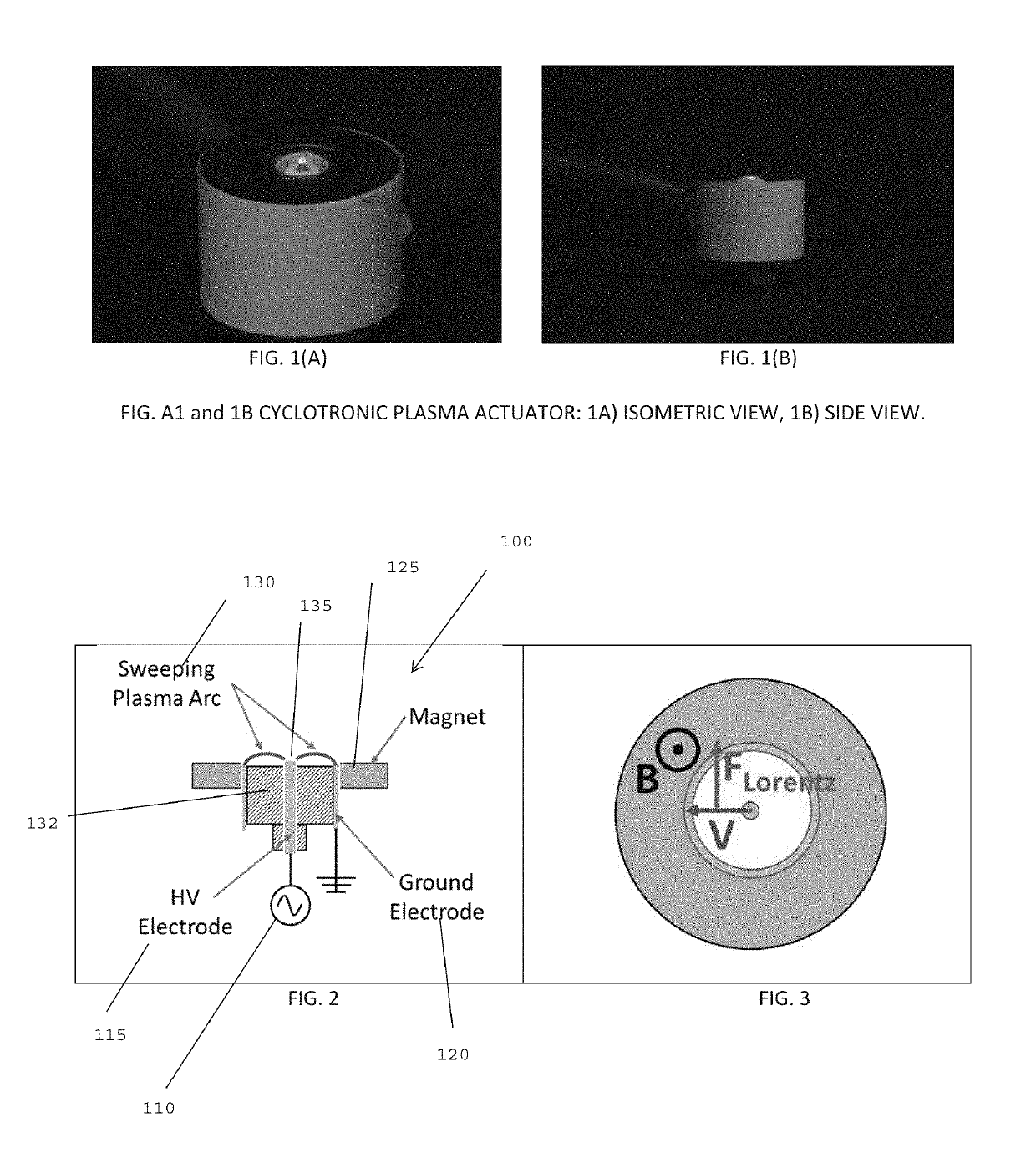
In an embodiment of the invention there is a cyclotronic actuator utilizing a high-voltage plasma driver connected to a first electrode. A second electrode is grounded and the two are isolated from each other by a dielectric plate. A magnet is positioned beneath the dielectric plate such that a coaxial dielectric barrier discharge plasma is formed outwardly between the first electrode across the dielectric plate. The magnet positioned beneath the dielectric plate introduces a magnetic field transverse to the plasma current path, such that the plasma discharge discharges radially and the local magnetic field is oriented vertically in a direction perpendicular to the dielectric plate to create a Lorentz Force, which forces the plasma discharge to move radially outwardly in a curved radial streamer mode pattern.

Description

CROSS REFERENCE TO RELATED APPLICATIONS[0001]The present application is a continuation in part of U.S. application Ser. No. 15 / 923,271 filed Mar. 16, 2018, which claims priority to U.S. Provisional Application 62 / 472,642 filed Mar. 17, 2017 and is hereby incorporated herein by reference.STATEMENT OF GOVERNMENT SUPPORT[0002]The invention was made with government support under NASA Langley Research Center on Contract Order #: NNX16CL76P.BACKGROUND OF THE INVENTION[0003]Various active flow control methodologies have emerged as a method for enabling advancement in efficiency and operational capabilities for fixed-wing aircraft. However, practical use of modern flow control techniques has been hindered by high power requirements, integration challenges, and insufficient control authority of existing methods. CU Aerospace (CUA) and the University of Illinois at Urbana-Champaign (UIUC) have teamed to develop an innovative cyclotronic arc-plasma flow control actuator, which can be utilized ...

Claims


Application Information

Patent Timeline
Patent Type & Authority Patents(United States)
IPC IPC(8): H04L27/156H01J37/32H05H1/50B64C23/00
Inventor ZIMMERMAN, JOSEPH W.CARROLL, DAVID L.ANSELL, PHILLIP J.HRISTOV, GEORGI
Owner CU AEROSPACE
Learn More