Frequency-conversion crystal for femtosecond-laser pulses
a technology of femtosecond laser pulses and crystals, which is applied in the field of frequency conversion crystals for femtosecond laser pulses, can solve the problems of limiting affecting the efficiency of frequency conversion, and affecting the crystal li
- Summary
- Abstract
- Description
- Claims
- Application Information
AI Technical Summary
Benefits of technology
Problems solved by technology
Method used
Image

Examples
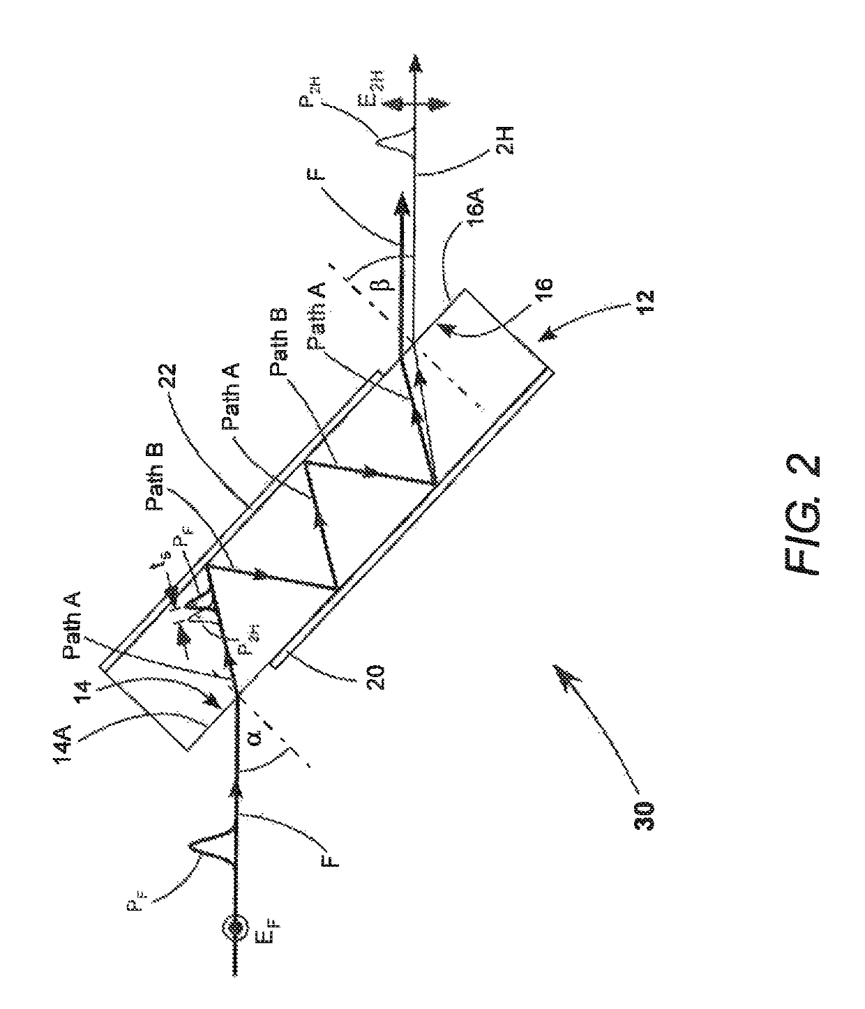
embodiment 30
[0020]In embodiment 30, entrance and exit facets 14 and 16 are partially coated with reflective coatings 20 and 22, respectively. The coatings are highly reflective for the fundamental wavelength and the second-harmonic wavelength. The coatings are disposed on the respective facets such that fundamental radiation F (pulse PF) is incident on a portion 14A of facet 14; enters crystal 12 at incidence angle α; is reflected from coating 22 onto coating 20; is reflected from coating 20 back to coating 22; is reflected again from coating 22 back to coating 20; and reflected from coating 20 out of crystal 12 via an uncoated portion 16A of facet 16. Portion 14A may be uncoated as depicted or furnished with an antireflection coating.
[0021]The forward path from facet 14 to facet 16 is designated here as Path A. The reverse path from facet 16 to facet 14 is designated here as Path B. The forward and reverse paths are at an angle to each other. Second-harmonic radiation is generated only during ...
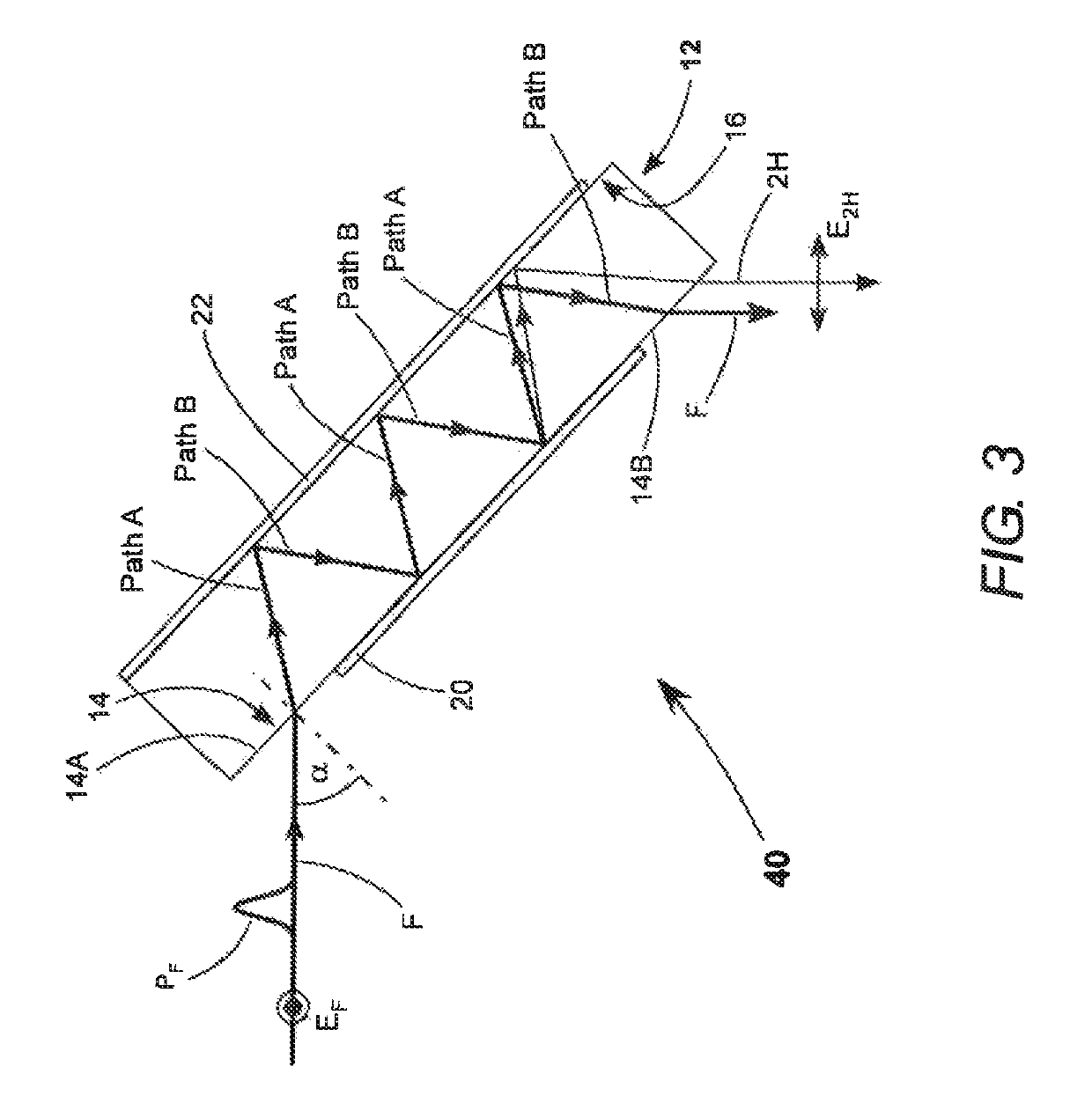
embodiment 40
[0033]If in the arrangement of FIG. 2 it were desired to re-synchronize the fundamental and second-harmonic pulses exiting the crystal, for example, for generating sum-frequency radiation in another frequency-conversion operation, this would require one or more additional birefringent elements. FIG. 3 schematically illustrates another preferred embodiment 40 of the present invention in which temporal synchronization of exiting fundamental and second-harmonic pulses can be achieved inherently.
[0034]The arrangement of embodiment 40 is similar to the arrangement of embodiment 30, with an exception that fundamental pulses enter and generated second-harmonic pulses and residual fundamental pulses exit crystal 12 via the same facet, here, facet 14. This is achieved in the example of FIG. 3 by extending the length of crystal 12, extending coating 22 to cover all of facet 16, and arranging coating 20 to leave uncoated portions 14A and 14B on facet 14. This allows for one additional Path B a...
PUM
| Property | Measurement | Unit |
|---|---|---|
| wavelength | aaaaa | aaaaa |
| wavelength | aaaaa | aaaaa |
| wavelength | aaaaa | aaaaa |
Abstract
Description
Claims
Application Information
 - R&D
- Intellectual Property
- Life Sciences
- Materials
- Tech Scout
- Unparalleled Data Quality
- Higher Quality Content
- 60% Fewer Hallucinations
Browse by: Latest US Patents, China's latest patents, Technical Efficacy Thesaurus, Application Domain, Technology Topic, Popular Technical Reports.
© 2025 PatSnap. All rights reserved.Legal|Privacy policy|Modern Slavery Act Transparency Statement|Sitemap|About US| Contact US: help@patsnap.com