
Dispenser apparatus and method of use for laminating and dispensing transfer tape in a paper web turn-up system

a technology of dispenser apparatus and turn-up system, which is applied in the direction of web handling, transportation and packaging, thin material handling, etc., can solve the problems of weakened or even substantially blinded adhesion, failure to transfer, and difficult high-speed transfer of lightweight paper webs, so as to prevent strong adhesion of the majority, prevent strong adhesion, and increase the width of the cover flap member

Active Publication Date: 2019-10-15
PAPELTEC OVERSEAS INC
View PDF46 Cites 1 Cited by
  • Summary
  • Abstract
  • Description
  • Claims
  • Application Information

AI Technical Summary

Benefits of technology

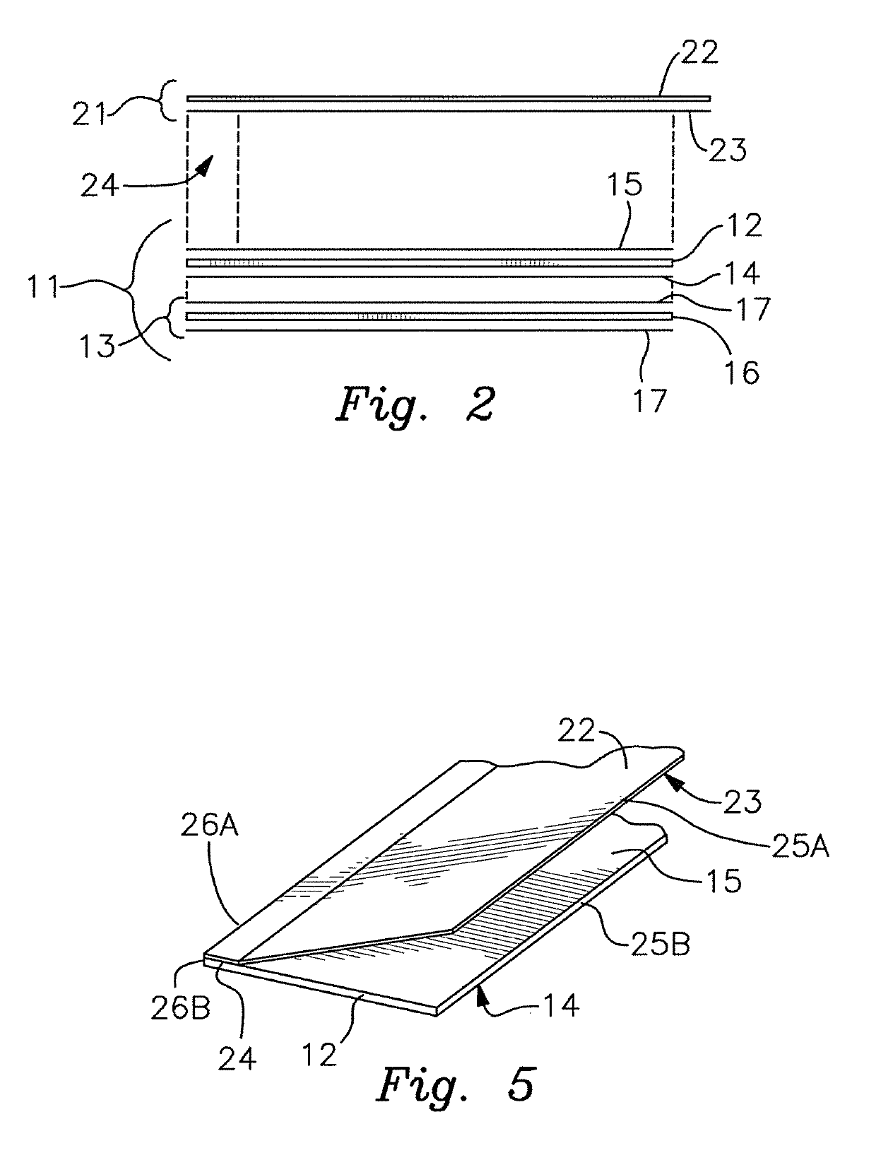
[0030]In one embodiment of the second tape component of the transfer tape the release coating on the cover flap member is a zone coating which covers the majority of the cover flap member surface but leaves a longitudinally extending strip along one edge of the cover flap member uncoated. The flap-covered transfer tape is produced by feeding the two tape components from the first and second transfer tape spools into a pressing mechanism such that the cover flap member adheres to the transfer tape substrate along the longitudinal edge that is void of release coating, with the release coated portion of the cover flap member extending across and facing the web-side PSA of the transfer tape substrate, thereby preventing strong adhesion of the majority of the cover flap member to the transfer tape substrate. With this construction, the cover flap member is effectively hinged to the transfer tape substrate of the first tape component along one edge.
[0031]In another embodiment for the second tape component of the transfer tape, the second tape component is a composite of a cover flap member having a release coating fully covering one side. The width of the cover flap member is greater than the width of the transfer tape substrate. To assemble the transfer tape components, one longitudinal edge of the cover flap member is folded such that a portion of the release coating abuts itself. When the tape components are fed through the roller press, the folded portion, which has no release coating on its exposed side, adheres to the web-side adhesive of the transfer tape substrate along one longitudinal edge. As with the first embodiment, the release coated side of the cover flap member extends across and faces the web-side PSA of the transfer tape substrate to prevent strong adhesion of the majority of the cover flap member to the web-side adhesive of the transfer tape substrate. As in the first embodiment, the cover flap member is now attached to the substrate in a longitudinally hinged manner.
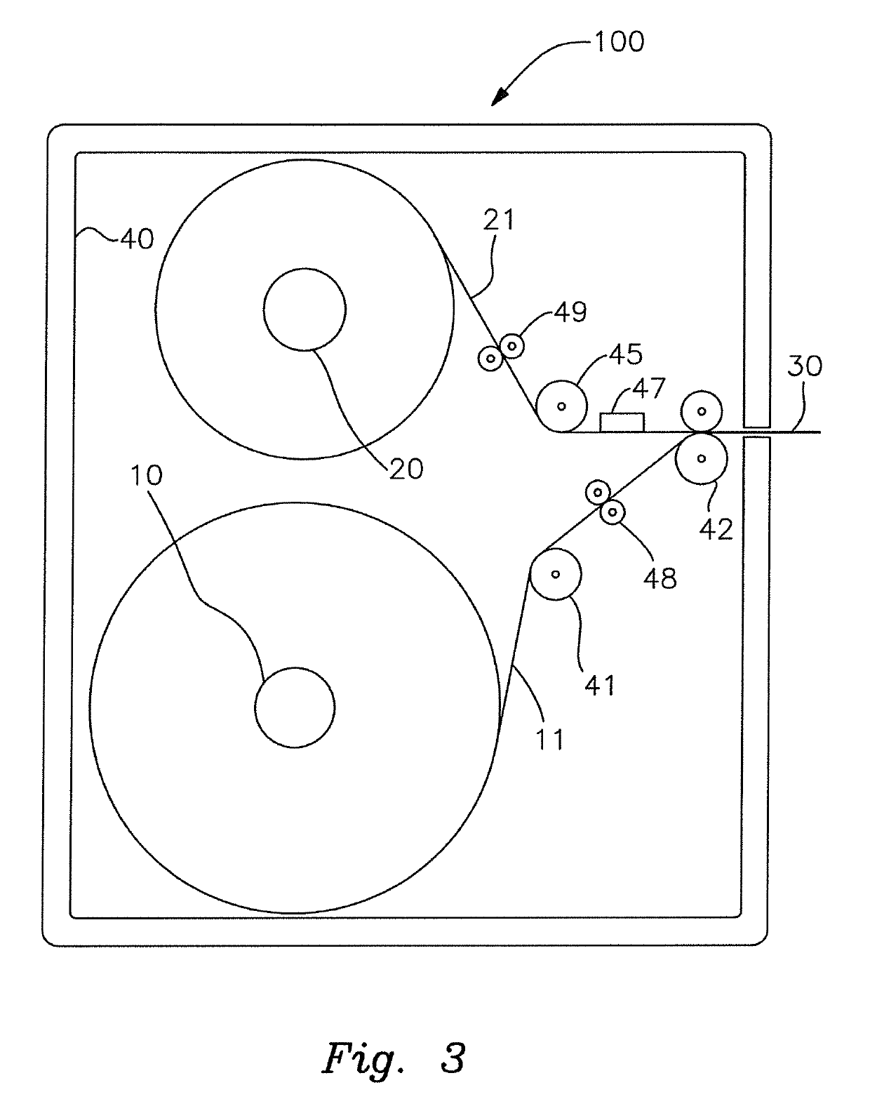
[0032]Preferably, the dispenser apparatus comprises a housing or enclosure which prevents dust and other particulates from contacting the components, especially the exposed PSA surfaces, while the first and second tape components are on their respective transfer tape spools and during the laminating operation, the laminated transfer tape being dispensed from the enclosure through a small slot. Most importantly, by dividing and storing the transfer tape within the dispenser housing as a first tape component on a first transfer tape spool and as a second tape component on a second transfer tape spool, a significantly greater length of transfer tape can be laminated and dispensed from a single dispenser apparatus. Storing the thinner second tape component on one transfer tape spool and storing the thicker first tape component on the other transfer tape spool alleviates buckling, delamination, excessive adhesion and other problems encountered when trying to store a laminated transfer tape on a single transfer tape spool. Thus, the size of the component transfer tape spools can be minimized, such that they occupy less space within the protective enclosure, and such that a greater length of transfer tape can be produced before the transfer tape spools are exhausted. The apparatus allows for the on-demand production of short segments of flat laminated transfer tape in optimal condition in the required length as needed for the web turn-up transfer operation. Multiple embodiments of the dispenser and methodologies for forming and dispensing the transfer tape are discussed and illustrated herein.
[0034]Alternatively still, the invention is summarized and described as a method of producing a transfer tape, said transfer tape being adapted to sever and secure a paper web from a first web spool onto an empty web spool in a web turn-up operation, said method comprising the steps of: providing a first tape component wound onto a first transfer tape spool, said first tape component comprising a transfer tape substrate having a width, a mounting-side adhesive disposed on one side of said transfer tape substrate, a web-side adhesive disposed on the opposite side of said transfer tape substrate, and a release liner disposed on said mounting-side adhesive; providing a second tape component wound onto a second transfer tape spool, said second tape component comprising a cover flap member having a width, a longitudinal edge and a release coating disposed on said cover flap member, wherein said release coating is zone-coated onto said cover flap member such that a longitudinally-extending uncoated joining strip is defined adjacent said longitudinal edge of said cover flap member; joining said first tape component to said second tape component to form a transfer tape by pressing together said web-side adhesive of said first tape component to said uncoated joining strip of said second tape component; and severing said transfer tape to separate the transfer tape from the first and second taper components. Furthermore, the invention further comprising the step of removing said release liner from said mounting-side adhesive; further comprising the step of adhering said mounting-side adhesive of said transfer tape to an empty web spool with said cover flap oriented to open to expose said web-side adhesive upon rotation of the empty web spool; further comprising the step of adhering said web-side adhesive to a paper web; wherein said step of joining said first tape component to said second tape component to form said transfer tape and said step of severing said transfer tape is performed immediately prior to said step of removing said release liner from said mounting-side adhesive and said step of adhering said mounting-side adhesive of said transfer tape to the empty web spool; wherein said step of adhering said mounting-side adhesive of said transfer tape to the empty web spool is performed manually; and / or further comprising the step of enclosing said first tape component and said second tape component to preclude particulate contamination of said mounting-side adhesive and said web-side adhesive.

Problems solved by technology

The high-speed transfer of lightweight paper webs, such as groundwood papers (including, for example, newsprint) or tissue paper, is more difficult to accomplish due to the weaker structure of the paper.
In addition, in systems using adhesive transfer tapes, the exposed adhesive side of the transfer tape is often contaminated with airborne dust, floating paper fibers and other debris, such that the adhesion is weakened or even substantially blinded, which can result in a failed transfer.
A failed transfer results in lost production, inconsistent winding of the product and inconsistent roll sizes, excessive waste, shorter service life of the fiber cores which are commonly used in tissue making machines, and unsafe operating conditions.
Multi-layer transfer tapes also suffer storage and shelf-life problems when produced and maintained in completed form as rolls or coils.
Unless the transfer tapes are exceedingly thin, which reduces strength and other desirable properties, variations in thicknesses and properties of the individual layers comprising the tape often result in buckling or delamination when the tape is unrolled from a storage spool or core.
In addition, certain configurations of transfer tape, such as for example a tape having thick substrate layer or longitudinal corrugations, cannot be wound without flattening the corrugations.
Furthermore, rolls of pre-manufactured transfer tapes may over time develop adhesion problems whereby the cover flap members may not readily release from the PSA adhesive.
Storage times as little as a few days may result in ineffective transfer tapes.
Any of these factors may result in undesirable adhesion between the release-coated portion of the cover flap member and the web-side adhesive layer of the transfer tape substrate.

Method used


Image

  • Dispenser apparatus and method of use for laminating and dispensing transfer tape in a paper web turn-up system
  • Dispenser apparatus and method of use for laminating and dispensing transfer tape in a paper web turn-up system
  • Dispenser apparatus and method of use for laminating and dispensing transfer tape in a paper web turn-up system

Examples


Embodiment Construction

[0039]With reference to the drawings, which are provided for illustrative and descriptive purposes and which are not meant to be limiting as to the scope of the invention, the invention in general embodiments comprises an apparatus and a method for assembling, i.e., laminating, and dispensing a multi-layer adhesive tape, and in particular wherein the multi-layer adhesive tape is a transfer tape used in a paper web turn-up operation, wherein a continuous paper web being rolled onto a first spool is severed and transferred to an empty spool when the first spool is fully wound, the transfer occurring without requiring the flow of the paper web to be temporarily altered, slowed or stopped. Multiple embodiments of the apparatus and method which produce different transfer tapes are illustrated and described. It is to be understood that disclosure of the apparatus and method in relation to a paper web turn-up operation is an exemplary disclosure not meant to be limiting, as the dispenser s...


PUM

PropertyMeasurementUnit
widthsaaaaaaaaaa
widthaaaaaaaaaa
pressure sensitiveaaaaaaaaaa

Abstract

An apparatus and method for assembling, dispensing and using a laminated paper web transfer tape, an embodiment of the apparatus having a pair of transfer tape spools enclosed within a cartridge dispenser, one transfer tape spool containing a first tape component of the laminated transfer tape and the other transfer tape spool containing a second tape component of the laminated transfer tape, the first tape component being the combination of a substrate having adhesive on both sides and a release liner, the second tape component being a cover flap member having a release coating over at least a majority of one side. The components are unwound from the spools and pressed together such that they become joined along a longitudinal edge strip, then dispensed from the housing. The cover flap member covers one of the adhesive sides of the transfer tape substrate until the moment just prior to transfer of a continuous paper web from a full web spool to an empty web spool, the cover flap member being opened to expose the adhesive by air pressure or resistance. The cartridge dispenser is removed retained within a dispenser frame.

Description

[0001]This application is a continuation-in-part of U.S. patent application Ser. No. 15 / 899,849, filed Feb. 20, 2018, claiming the benefit of U.S. Provisional Patent Application Ser. No. 62 / 510,448, filed May 24, 2017.BACKGROUND OF THE INVENTION[0002]This invention relates generally in a first sense to the field of devices, apparatuses and methods of effecting the high-speed severing and transfer of a rapidly advancing paper web from a rotating full spool onto an empty spool, and more particularly where such an operation is performed utilizing a transfer or double-sided adhesive turn-up tape. More particularly, the invention relates to an apparatus and method for laminating, i.e., assembling, and dispensing transfer tape and its use in a paper web severing / transfer method, wherein the transfer tape is the effecting means for severing, transferring and securing the paper web from a rotating full spool onto an empty spool. Additionally, the invention relates in general to a tape dispe...

Claims


Application Information

Patent Timeline
Patent Type & Authority Patents(United States)
IPC IPC(8): B65H19/10B65H19/28
CPCB65H19/102B65H2301/46072B65H19/286B65H2301/46078
Inventor RODRIGUEZ, PETERRODRIGUEZ, JASONDOHOGNE, DENNIS A
Owner PAPELTEC OVERSEAS INC
Learn More