
Intraocular lens

a technology of intraocular lens and lens plate, which is applied in the field of intraocular lens, can solve the problems of affecting the quality of intraocular lens, and unable to overcome adhesion with recovery force sufficient, so as to prevent strong adhesion, easy and stable position and support, and easy and stable positioning

Inactive Publication Date: 2009-03-26
KOWA CO LTD
View PDF28 Cites 14 Cited by
  • Summary
  • Abstract
  • Description
  • Claims
  • Application Information

AI Technical Summary

Benefits of technology

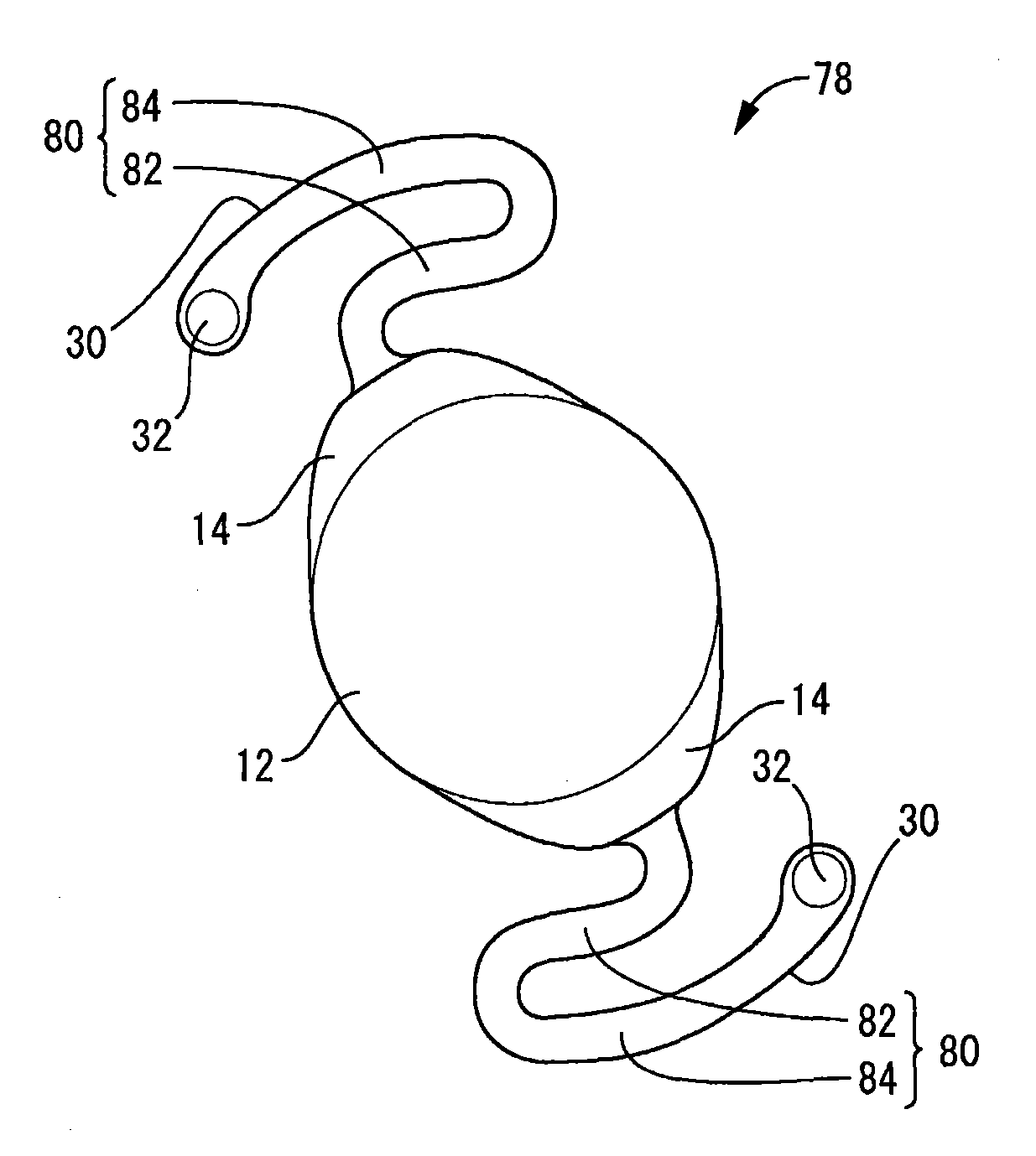
[0035]As will be apparent from the preceding description, in the intraocular lens of structure according to the present invention, by means of the viscosity reducing portions formed on the supporting portions it is possible to prevent strong adhesion between the superposed faces of the optical portion and the supporting portions in association with folding or rolling of the intraocular lens for insertion into the capsule. Therefore, the supporting portions can easily recover their original shape after insertion into the capsule, and can easily and stably position and support the optical portion at the prescribed location within the capsule.

Problems solved by technology

However, even if the incision made during surgery is small, if the intraocular lens being inserted is large in size relative to the size of the incision, the incision which has deliberately been made small will inevitably become enlarged during insertion.
Thus, when the intraocular lens is folded or rolled (this includes curling, rolling, etc.) during the process of inserting the intraocular lens into the capsule, there is a risk that superposed surfaces of the optical portion and the supporting portions will adhere together so that [the lens] does recover its initial shape despite the resilience of the optical portion and the supporting portions.
In particular, since the supporting portions are of thin, elongated rod form, where they are made soft enough to permit folding or rolling it will be difficult to also endow them with recovery force sufficient to overcome adhesion.
On the other hand, while it would be conceivable to make the supporting portions larger so as to easily overcome adhesion, making the supporting portions larger will not only make folding or rolling more difficult, but also poses the problem of a larger burden on the patient, due to enlargement of the incision wound during insertion into the capsule.

Method used


Image

  • Intraocular lens
  • Intraocular lens
  • Intraocular lens

Examples


first embodiment

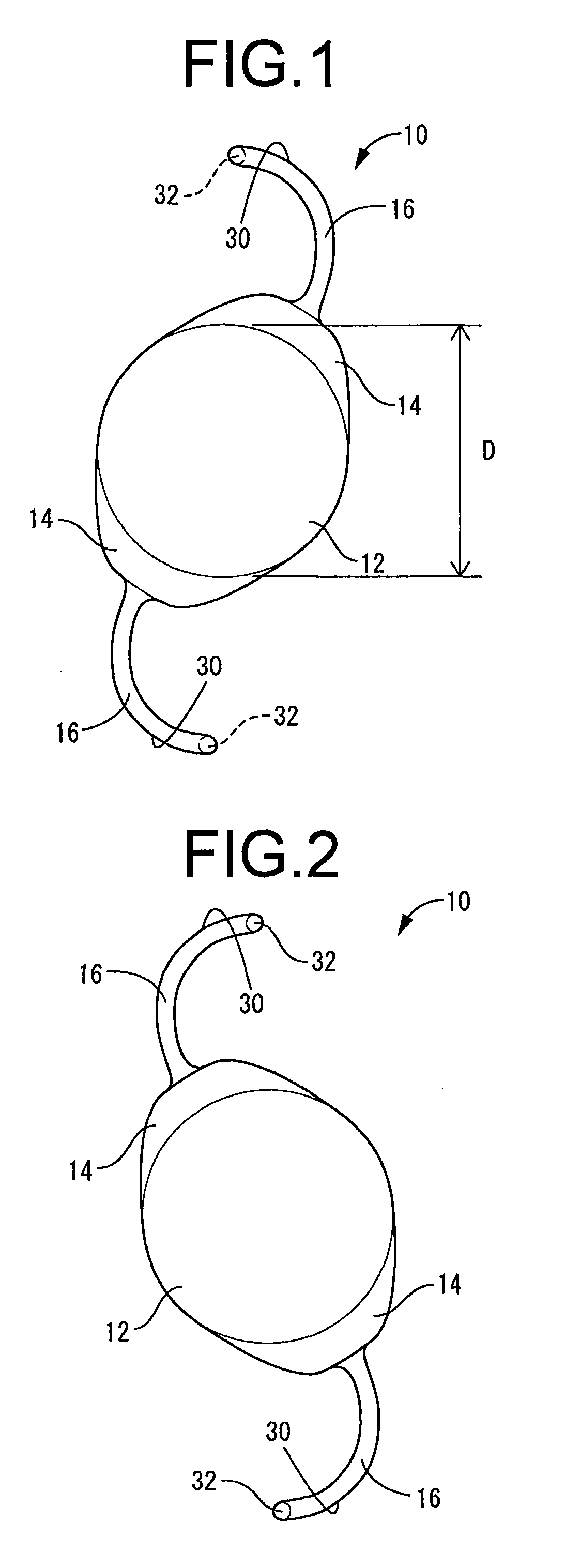
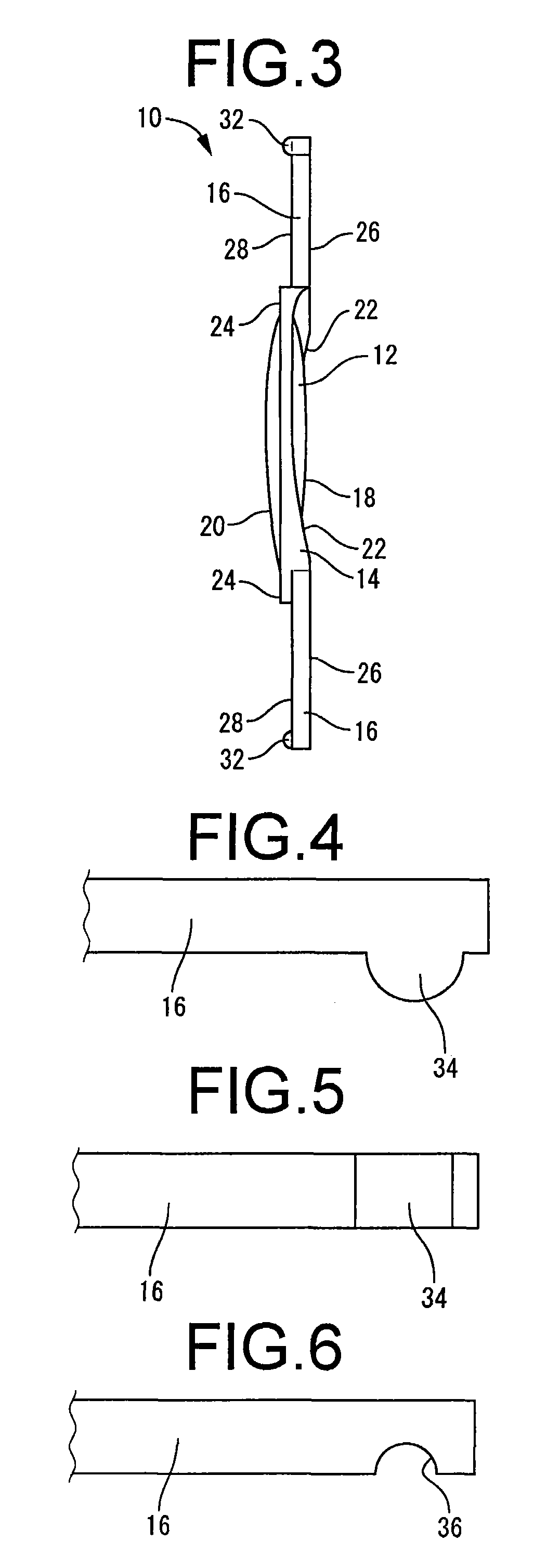
[0085]First, FIGS. 1 through 3 depict an intraocular lens 10 of foldable type, pertaining to the present invention. This intraocular lens 10 includes an optical portion 12, a pair of coupling portions 14, 14, and a pair of supporting portions 16, 16.

[0086]This intraocular lens 10 having the optical portion 12, the coupling portions 14, 14, and the supporting portions 16, 16 may be formed of any of various materials endowed with visible light transmissivity sufficient to give an intraocular lens of foldable type, and endowed with excellent softness and certain amount of elasticity. In preferred practice, the soft material will have glass transition temperature of 30° C. or higher and refractive index of 1.51 or lower. Such soft materials enable the intraocular lens 10 to be easily folded or rolled up at normal temperature, so as to make it more compact as well as further facilitating insertion into the eye during the implantation process. In the present embodiment in particular, an a...

second embodiment

[0132]FIGS. 4 and 5 depict the relevant portion of an intraocular lens pertaining to the present invention. In the intraocular lens pertaining to the present embodiment, a single rib part 34 is formed as a viscosity reducing portion, on the supporting portion posterior surface 28 of the pair of supporting portions 16, 16. This rib part 34 extends continuously with a generally unchanging semicircular cross section in the width direction of the supporting portions 16, 16, and is constituted so as to have a bowing surface which is convex towards the side to which the rib part 34 projects.

[0133]The intraocular lens of structure according to the present embodiment affords effects similar to those of the first embodiment in that it effectively prevents adhesion of the supporting portions 16, 16 to the optical portion 12, and enables consistent recovery of the supporting portions 16, 16 to their original shape after insertion into the eye. Moreover, in the present embodiment in particular,...

third embodiment

[0134]FIGS. 6 and 7 depict the relevant portion of an intraocular lens pertaining to the present invention. Specifically, in the intraocular lens pertaining to the present embodiment, a single recess 36 that opens onto the posterior face side of the supporting portions 16, 16 is formed by way of a viscosity reducing portion. The recess 36 is formed so as to extend through the projecting distal end portion of the supporting portions16, 16, with generally unchanging semicircular cross section in the width direction of the supporting portions 16, 16 and with the widthwise ends of the recess opening onto the widthwise side edges of the supporting portions 16, 16.

[0135]The intraocular lens of structure according to the present embodiment affords reduced contact area of the projecting distal end portions of the supporting portions 16, 16, which have the problem of being particularly prone to adhesion, vis-à-vis other areas (the optical surface of the optical portion 12 and so on), and can...


PUM


Abstract

A one-piece intraocular lens realizing adhesion of the intraocular lens to the inner surface of a capsule more advantageously by viscosity imparted to the intraocular lens, and being deployed more positively after it is inserted into the capsule and secured therein while being positioned at a specified location. The intraocular lens has an optical portion (12) and supporting portions (16, 16) that are formed integrally with a soft material exhibiting viscosity, wherein viscosity reducing portions (32, 32) having irregularities are formed on at least one-end faces of the supporting portions (16, 16) in the longitudinal direction.

Description

TECHNICAL FIELD[0001]The present invention relates to an intraocular lens of one-piece design in which the optical portion and the supporting portions are integrally formed of soft material; and relates in particular to an intraocular lens able to be deformed by means of folding or rolling into a more compact shape for insertion into the eye.BACKGROUND ART[0002]One well-known method used in the past for treating the ocular disorder known as a cataract involves removing the lens of the eye, and employing an intraocular lens as a substitute for the lens. An intraocular lens of this kind is used by being inserted into the capsule from which the lens has been removed; the lens has an optical portion, which functions in place of the lens of the eye, and a support portion for positioning and immobilizing the optical portion within the capsule.[0003]In cataract treatment employing an intraocular lens of this kind, an incision is made in part of the patient's eye, the lens of the eye is wit...

Claims


Application Information

Patent Timeline
Patent Type & Authority Applications(United States)
IPC IPC(8): A61F2/16
CPCA61F2002/1683A61F2/1613A61F2/16A61F2250/0025A61F2250/0026A61F2250/0034A61F2002/1681
Inventor MARUNAKA, AKINORITANAKA, MASAYOSHI
Owner KOWA CO LTD
Learn More