
Multi-state clip-on fixation method for pulse oximeter

a multi-state, clip-on technology, applied in the field of multi-state clip-on fixation method for pulse oximeter, can solve the problems of difficult manipulation, tissue necrosis, pain and discomfort of patients, etc., and achieve the effect of increasing patient comfor

Active Publication Date: 2019-10-15
KONINKLJIJKE PHILIPS NV
View PDF18 Cites 2 Cited by
  • Summary
  • Abstract
  • Description
  • Claims
  • Application Information

AI Technical Summary

Benefits of technology

The solution provides a secure, comfortable, and easy-to-use pulse oximeter that can be attached to small body parts without causing discomfort or falling off, ensuring accurate measurements and increased patient safety.

Problems solved by technology

The “clip on” design has the potential to pinch the finger, earlobe, or other target location, which can cause pain and lead to tissue necrosis.
For example, the devices can fully close and pinch the patient, thereby causing pain and discomfort to the patient.
Designs including an applicator are complex two-piece components that can be difficult to manipulate, and the applicator is a separable component.
As a result, the applicator can often become lost and thus unavailable when a nurse needs it to remove the sensor from the patient.
If an applicator is unavailable when the nurse or other medical person is removing the pulse oximeter, there is a temptation to remove it without using an applicator, which can be uncomfortable for the patient.
In addition, the sensor can be clamped incorrectly (i.e., loosely) on the patient, and fall off during use.
In addition, the mechanism does not easily fall off without a force applied thereto.

Method used


Image

  • Multi-state clip-on fixation method for pulse oximeter
  • Multi-state clip-on fixation method for pulse oximeter
  • Multi-state clip-on fixation method for pulse oximeter

Examples


Embodiment Construction

[0028]It is recognized herein that existing pulse oximeter designs have certain deficiencies. The “clip on” design has the potential to pinch the finger, earlobe, or other target location, which can cause pain and lead to tissue necrosis (e.g., by fully closing and thus pinching the patient). Designs including an applicator are complex two-piece devices that can be difficult to manipulate, and the applicator is a disposable component, which can often be lost or misplaced. If an applicator is unavailable when the nurse or other medical person is removing the pulse oximeter, there is a temptation to remove the pulse oximeter without using an applicator, which can be uncomfortable for the patient. In addition, the sensor can be clamped loosely on the patient, and thus fall off during use

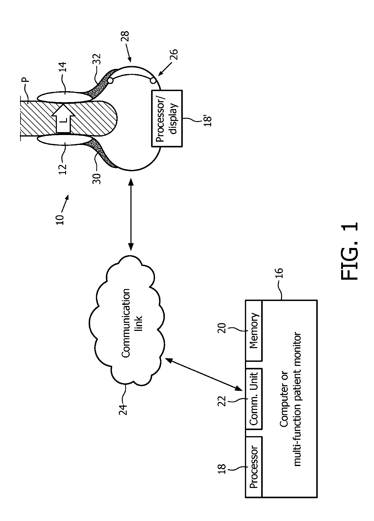
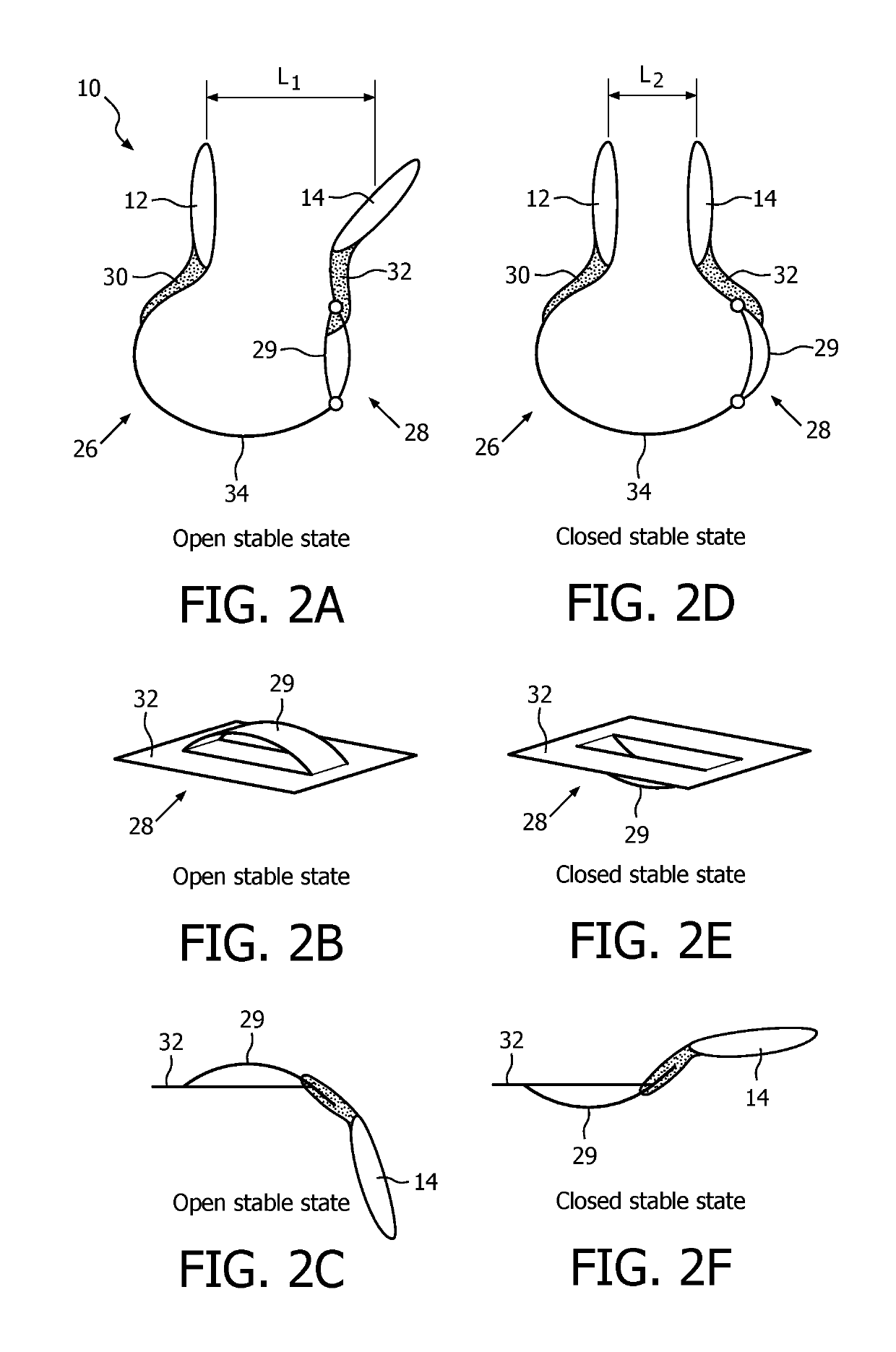
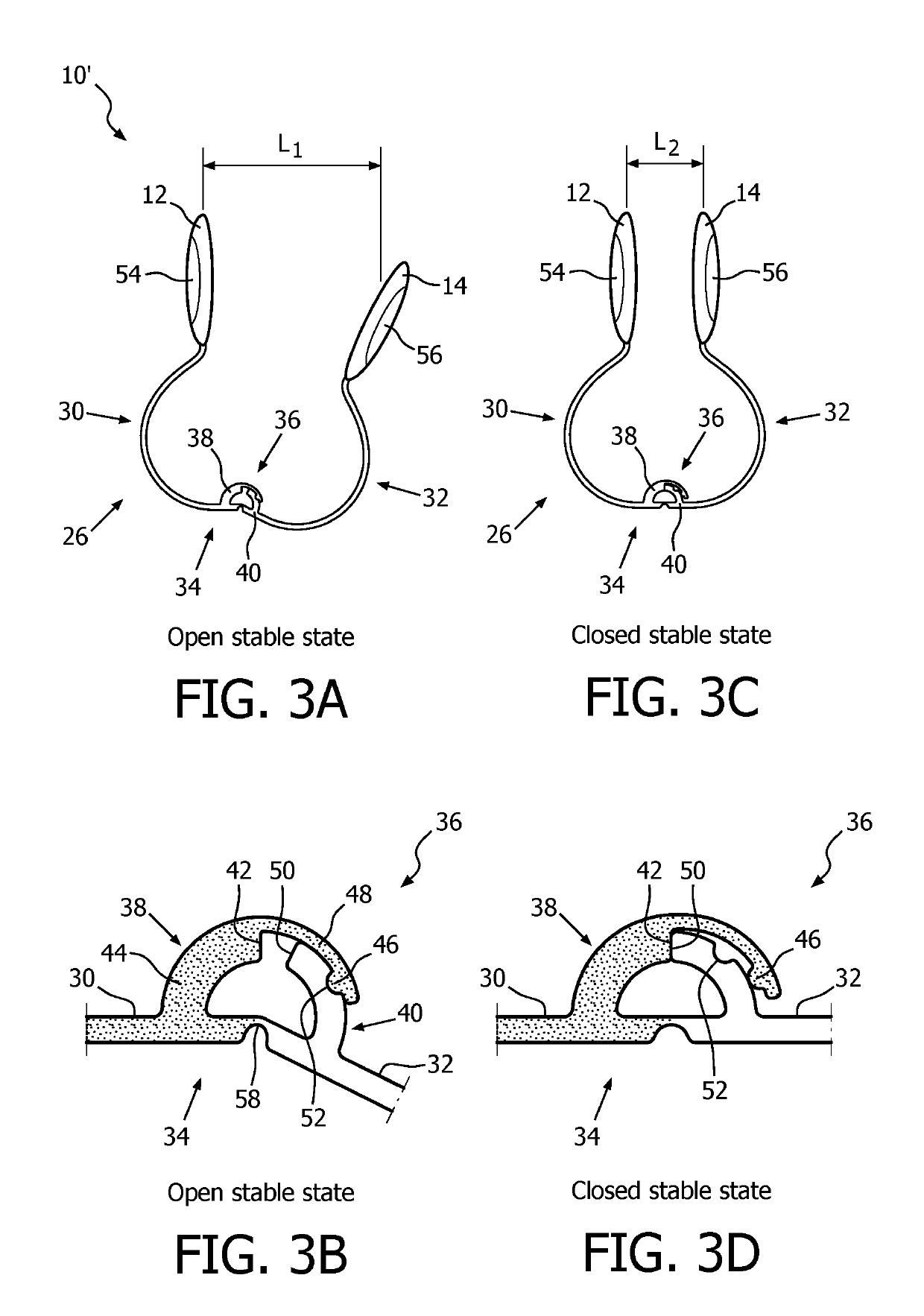
[0029]Pulse oximeters disclosed herein comprise a clamping member with a bi-stable hinge that is transitionable between a stable open state and a stable closed state. With reference to FIG. 1, the devic...


PUM


Abstract

A device (10, 10′, 10″) includes a light source (12) and a light detector (14) spaced from, and in communication with, the light source (12). An electronic processor (18) is programmed to compute pulse oximetry data from output of the light detector (14). A clamping member (26) is included, on or in which the light source (12) and the light detector (14) are disposed. The clamping member (26) is configured for attachment to a human body part with the body part disposed between the light source (12) and the light detector (14) such that light from the light source (12) passes through the body part to reach the light detector (14). The clamping member (26) is configured to attach to the body part by transitioning from a first stable state to a second stable state via a compression force applied to the clamping member (26).

Description

CROSS REFERENCE TO RELATED APPLICATIONS[0001]This application is the U.S. National Phase application under 35 U.S.C. § 371 of International Application No. PCT / IB2016 / 050951, filed Feb. 23, 2016, published as WO 2016 / 135617 on Sep. 1, 2016, which claims the benefit of U.S. Provisional Patent Application No. 62 / 119,461 filed on Feb. 23, 2015. These applications are hereby incorporated by reference herein.FIELD[0002]The following relates generally to measuring indications of pulse rate and arterial oxygen saturation (SpO2) of a patient. It finds particular application in conjunction with a pulse oximeter of the “clip-on” type in which the pulse oximeter clips onto a finger, earlobe, or so forth. However, it is to be understood that it also finds application in other usage scenarios and is not necessarily limited to the aforementioned application.BACKGROUND[0003]Pulse oximetry has become a standard of care in clinical practice. It provides a continuous non-invasive readout of criticall...

Claims


Application Information

Patent Timeline
Patent Type & Authority Patents(United States)
IPC IPC(8): A61B5/1455A61B5/024A61B5/00
CPCA61B5/0002A61B5/0205A61B5/02427A61B5/02438A61B5/14552A61B5/6816A61B5/6819A61B5/6826A61B5/6838A61B5/6843
Inventor PEETERS, WOUTER HERMANJACOBS, EGBERTUS REINIERBEZEMER, RICKMUEHLSTEFF, JENS
Owner KONINKLJIJKE PHILIPS NV
Learn More