
Composite structures having embedded mechanical features

a composite structure and mechanical feature technology, applied in the field of fiber reinforced composite structures, can solve the problems of poor mechanical properties when machined or drilled, significant weakening, and engineering art that requires considerable skill, and achieves the effects of minimizing structural weight, minimizing buckling, warping, distortion, and minimizing structural weigh

Active Publication Date: 2019-10-08
VISION COMPOSITE PROD LLC +1
View PDF43 Cites 0 Cited by
  • Summary
  • Abstract
  • Description
  • Claims
  • Application Information

AI Technical Summary

Benefits of technology

The present invention is about a method for making complex-shaped fiber reinforced composite structures with embedded mechanical features. The method involves arranging a plurality of pressurizable members with a desired shape and placing layers of fiber plies onto the pressurizable members. A mechanical feature is then placed on top of the fiber plies and another layer of fiber plies is placed over the mechanical feature to encapsulate it. The assembly is then placed in a tool and subjected to internal and external pressures to compress the fiber plies around the mechanical feature while minimizing voids between the fiber plies and the mechanical feature. The technical effect of this invention is the ability to make complex-shaped composite structures with embedded mechanical features while minimizing weight and maintaining sufficient load carrying and load transferring capabilities.

Problems solved by technology

However, even the hardest, toughest, and strongest composite materials are considered “soft” when compared to high strength metals, and have poor properties when machined or drilled.
Specifically, drilling a fastener hole cuts the fibers within the structure and, therefore, significantly weakens it.
Therefore, attaching a composite component to a metallic fitting or vice-versa is an engineering art that requires considerable skill.
Regardless of hardware (nuts, bolts, washers, etc.), mechanical fastening is limited by its inherent process of cutting fibers (drilling and countersinking a hole), and forcing mating surfaces together—thereby crushing (and potentially exceeding the compressive strength of the composite material.
It is not uncommon for bolts to pull through composite materials because joint loads exceed capability.
The thicknesses of composite material should compensate for the cut fibers and low compressive strength, which typically results in additional composite material, and thus additional weight.
This extra material is considered parasitic weight that is theoretically unnecessary, except for its function at the joint.
Although it is theoretically possible to bond a metallic fitting to a composite article, either during or after the composite article manufacturing process, aircraft materials and process experts rarely allow those bonds to be considered in structural applications.
Depending on configuration, this approach can result in a failsafe design.
However, this approach has very limited configurations that are useful since most are circular or rectangular by necessity.

Method used


Image

  • Composite structures having embedded mechanical features
  • Composite structures having embedded mechanical features
  • Composite structures having embedded mechanical features

Examples


Embodiment Construction

[0046]In the following description, certain specific details are set forth in order to provide a thorough understanding of various embodiments of the invention. However, one skilled in the art will understand that the invention may be practiced without these details. In other instances, well-known structures associated with composite structures, the tooling to produce the same, and methods of making, configuring and / or operating any of the above have not necessarily been shown or described in detail to avoid unnecessarily obscuring descriptions of the embodiments of the invention.

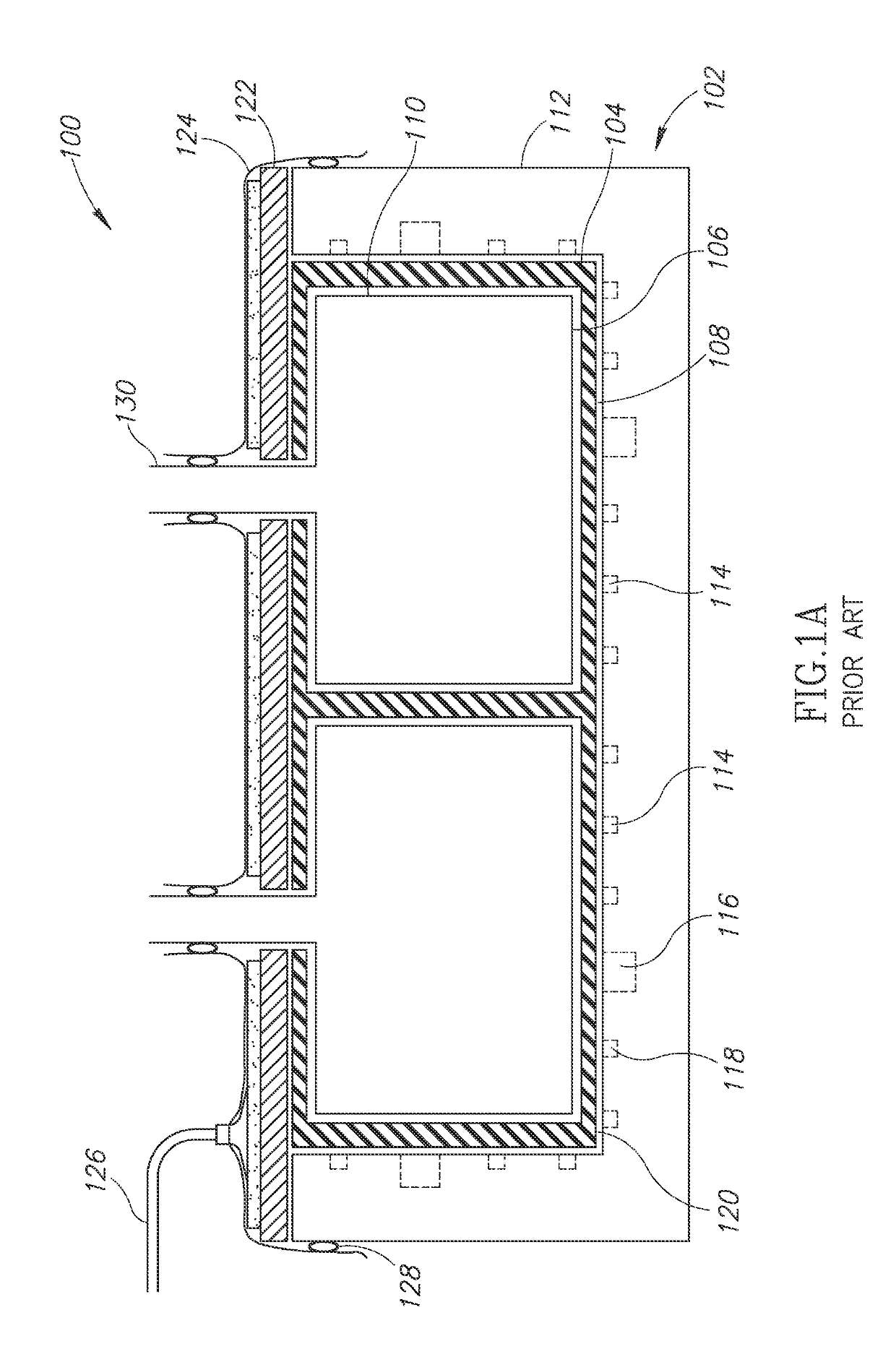
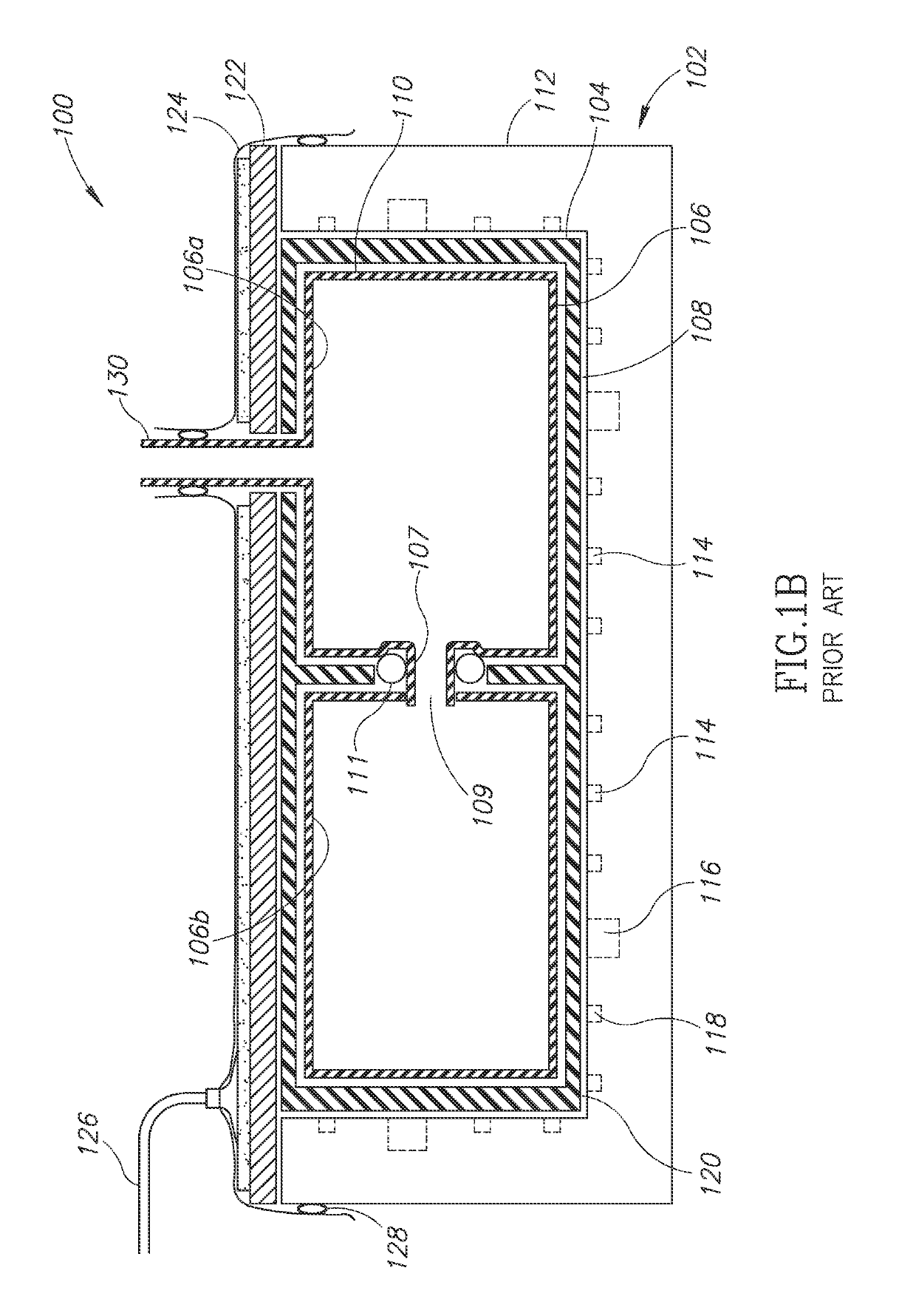
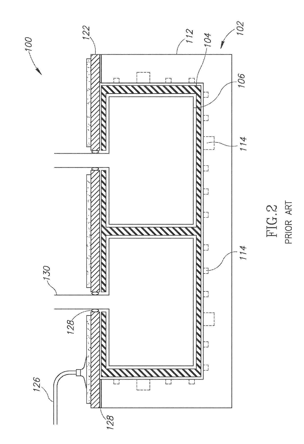
[0047]The present invention is generally directed to the inclusion of mechanical features within a composite structure. U.S. patent application Ser. Nos. 11 / 835,261; 12 / 176,981; 12 / 330,391; and 12 / 565,602 describe how pressurizable members may be arranged to produce complex-shaped composite assemblies and / or structures, and those patent applications are hereby incorporated by reference in their entireties. ...


PUM

PropertyMeasurementUnit
structureaaaaaaaaaa
mechanicalaaaaaaaaaa
internal pressureaaaaaaaaaa

Abstract

A complex-shaped, three-dimensional fiber reinforced composite structure may be formed by using counteracting pressures applied to a structural lay-up of wetted fibers with mechanical features embedded or encapsulated therein. The mechanical features may be located on or at least partially between two or more pressurizable members, which may be internally pressurized within a mold. The mechanical features may operate as bearing plates, attachment fittings, or other structural elements. Assemblies of pressurizable members, fiber plies and mechanical features may be arranged to create complex composite structures with predefined load paths, enhanced structural capability or both.

Description

PRIORITY CLAIM[0001]This application claims priority from U.S. Provisional Patent Application No. 61 / 897,924 filed on Oct. 31, 2013; this application also claims the benefit of and is related to U.S. Patent Publication No. 2013 / 0154154; and the subject matter of each application is incorporated herein by reference in its entirety.FIELD OF THE INVENTION[0002]The present invention generally relates to fiber-reinforced composite structures having one or more encapsulated or embedded mechanical features, and methods for manufacturing such composite structures.BACKGROUND[0003]Metal structures have conventionally been used to create fittings, provide bearing surfaces and attachment means because metal is readily machine-able and typically more easily inspected as compared to fiber-reinforced composite structures. Metallic fittings are used in extensively in aircraft structures as interfaces between structural components, such as between a landing gear door and an aircraft fuselage. Metall...

Claims


Application Information

Patent Timeline
Patent Type & Authority Patents(United States)
IPC IPC(8): B32B38/00B29C70/70B29C70/86B29C70/48B29L31/30
CPCB29C70/865B29C70/70B29C70/48Y10T156/1002B29L2031/3076
Inventor RODMAN, WILLIAM L.
Owner VISION COMPOSITE PROD LLC
Learn More