
Motor controller and electronically commutated motor comprising the same

a technology of motor controller and electronic commutation, which is applied in the direction of electronic commutators, dc-ac conversion without reversal, instruments, etc., can solve the problems of reducing transmission efficiency, increasing the burden of common i/o ports, and large space of controllers,

Active Publication Date: 2019-09-24
ZHONGSHAN BROAD OCEAN
View PDF16 Cites 0 Cited by
  • Summary
  • Abstract
  • Description
  • Claims
  • Application Information

AI Technical Summary

Benefits of technology

[0005]In view of the above-described problems, it is one objective of the invention to provide a motor controller and an ECM comprising the same. The motor controller has a relatively low occupancy rate on the common I / O port of the microprocessor, which reduces the cost and improving the transmission efficiency.
[0015]1. One rotation speed input signal of a motor is transmitted to the signal identification unit of the microprocessor via the isolation circuit and the PWM input line, and the signal identification unit determines whether an input signal of the PWM input line is a PWM signal or a rotation speed input signal of the motor. Thus, the microprocessor is fully utilized, reducing the occupancy rate of the I / O ports by the rotation speed input lines, simplifying the structure of the controller (one external lead wire is omitted), and saving the production costs.
[0017]3. The signal identification unit is a hardware unit, for example, a spectrum identifier, or a software unit, both are easily available.

Problems solved by technology

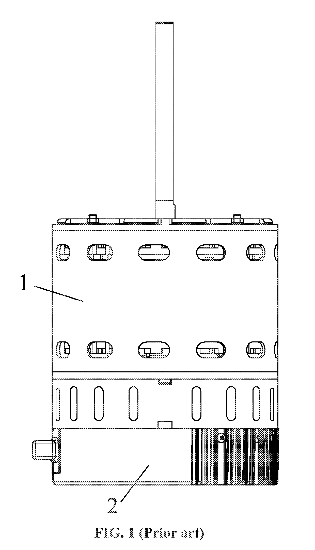
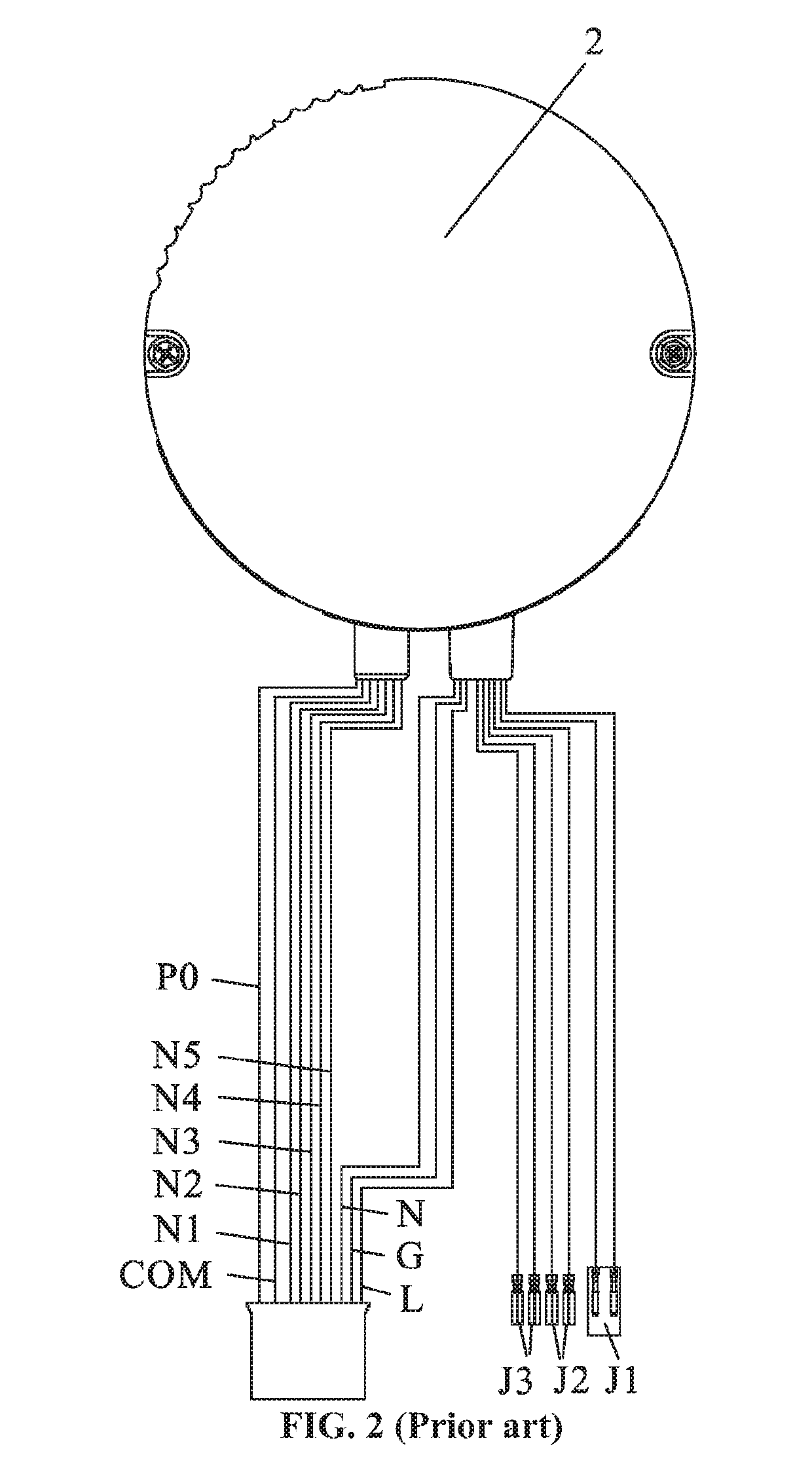
Thus, a plurality of lead wires is disposed on the motor controller 2, occupying a relatively large space of the controller contributing to increased costs.
In addition, most of the lead wires are connected to a common I / O port of the microprocessor, increasing the burden of the common I / O port and reducing the transmission efficiency.

Method used


Image

  • Motor controller and electronically commutated motor comprising the same
  • Motor controller and electronically commutated motor comprising the same
  • Motor controller and electronically commutated motor comprising the same

Examples


example 1

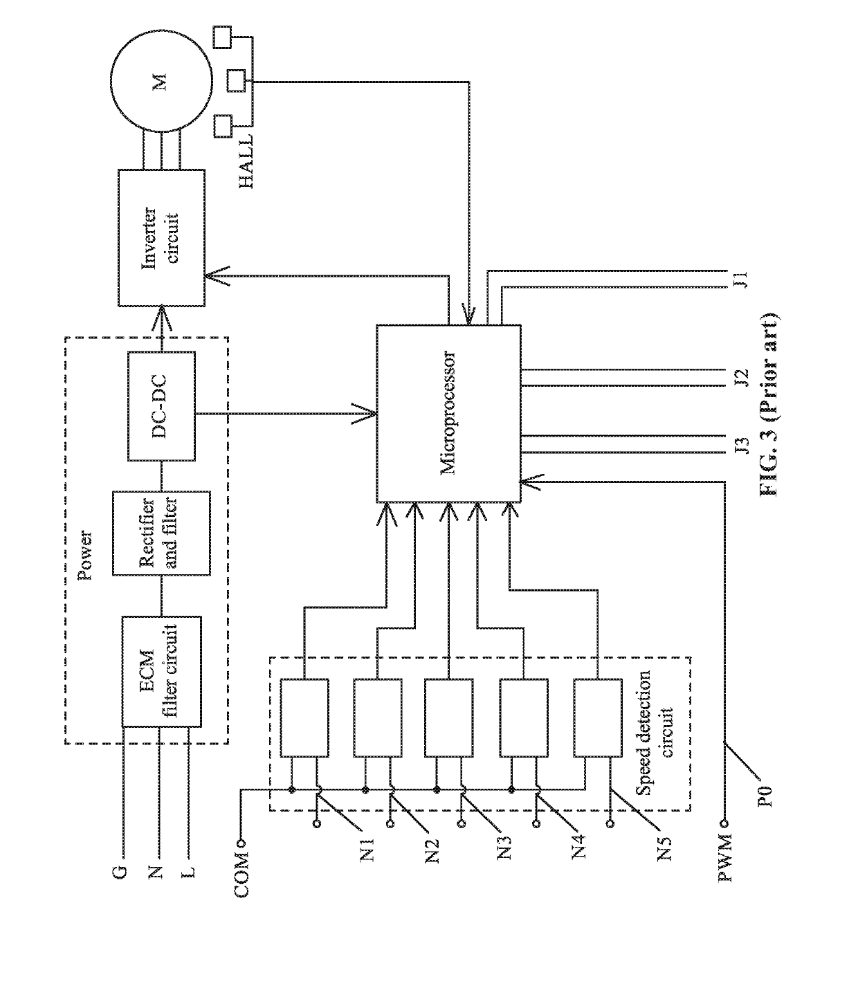
[0025]As shown in FIGS. 4-5, a motor controller for ECMs comprises: a microprocessor; an inverter circuit; a rotation speed detection circuit; a power module; and an isolation circuit. The components are disposed on the control circuit board. The power module comprises an ECM filter, a rectifier filter, and a DC-DC converter. The input end of the ECM filter is connected to the AC input. The output end of the ECM filter is connected to the input end of the rectifier filter. The rectifier filter outputs a bus voltage and is connected to the DC-DC converter. The DC-DC converter outputs +15 V, +5 V alternately. The bus voltage, +15 V, and +5 V supplies the circuits. The Hall element detects the motor rotor position signal and transmits the signal to the microprocessor, and the microprocessor controls the operation of the motor via the inverter circuit.

[0026]The motor controller communicates with five rotation speed input signals S1, S2, S3, S4, and S5, and one PWM signal for motor speed...

example 2

[0030]An electronically commutated motor (ECM) comprises the motor controller disclosed in Example 1 and a motor body. The motor body comprises a rotor assembly, a stator assembly, and a housing assembly.


PUM


Abstract

A motor controller, including: a microprocessor including a signal identification unit; an inverter circuit; a rotation speed detection circuit; a power module; and an isolation circuit. The power module supplies power for the microprocessor, the inverter circuit, the rotation speed detection circuit, and the isolation circuit. The isolation circuit is connected to the microprocessor via a pulse width modulation (PWM) input line, and a PWM signal is transmitted to the isolation circuit and the microprocessor successively via the PWM input line. One rotation speed input signal of a motor is transmitted to the signal identification unit of the microprocessor via the isolation circuit and the PWM input line. The signal identification unit determines whether an input signal of the PWM input line is the PWM signal or the one rotation speed input signal of the motor.

Description

CROSS-REFERENCE TO RELATED APPLICATIONS[0001]This application is a continuation-in-part of International Patent Application No. PCT / CN2016 / 098490 with an international filing date of Sep. 8, 2016, designating the United States, now pending, and further claims foreign priority benefits to Chinese Patent Application No. 201620340982.3 filed Apr. 21, 2016. The contents of all of the aforementioned applications, including any intervening amendments thereto, are incorporated herein by reference. Inquiries from the public to applicants or assignees concerning this document or the related applications should be directed to: Matthias Scholl P. C., Attn.: Dr. Matthias Scholl Esq., 245 First Street, 18th Floor, Cambridge, Mass. 02142.BACKGROUND OF THE INVENTIONField of the Invention[0002]The disclosure relates to a motor controller and an electronically commutated motor (ECM) comprising the same.Description of the Related Art[0003]Conventional ECMs have 5-6 rotation speed input lines for sele...

Claims


Application Information

Patent Timeline
Patent Type & Authority Patents(United States)
IPC IPC(8): H02P27/08H02P6/16H02P6/04H02P6/14H02P4/00H02K11/20H02M7/44H02M1/00G01D5/14H02K11/33
CPCH02M7/44H02P6/04H02P27/08H02P4/00H02P6/16H02K11/20H02P6/14H02K11/33H02M2001/0006G01D5/145H02M1/0006
Inventor BIAN, WENQINGZHANG, DI
Owner ZHONGSHAN BROAD OCEAN
Learn More