
Numerical controller that prevents a tool compensation value setting error

a technology of compensation value and numerical controller, applied in the field of numerical controller, can solve the problems of easy error in tool compensation value setting error, workpieces cannot be finished to desired dimensions, and it is not possible to perform desired machining, etc., to achieve the effect of preventing the error in the compensation value setting

Active Publication Date: 2019-09-17
FANUC LTD
View PDF14 Cites 0 Cited by
  • Summary
  • Abstract
  • Description
  • Claims
  • Application Information

AI Technical Summary

Benefits of technology

This approach enables accurate setting of tool compensation values, preventing errors by clearly showing the influence of changes on the tool cutting edge's position relative to the workpiece, thereby ensuring precise machining dimensions are met without manual intervention.

Problems solved by technology

Since the amount and direction of protrusion from the tool holder differs according to the tools, it is not possible to perform desired machining unless a positional relationship between a reference position of the tool holder (a position recognized or controlled by the numerical controller) and the tool cutting edge is registered with the numerical controller in advance.
In reality, however, there may be a case where the workpiece can not be finished to desired dimensions because of wear of the tool, a temperature condition, a mechanical factor and the like.
Therefore, there is a problem that a tool compensation value setting error easily occurs.
Thereby, manual setting is unnecessary.
In the case of changing a tool compensation value for purposes other than the above, however, there is a problem that it is not possible to prevent a tool compensation value setting error.
In this case, if a tool compensation value set by measuring a tool or a tool compensation value set using the tool setter described before is used as it is to perform machining, there is a possibility of shaving off too much.
Since there is a possibility of shaving off too much if the whole dimension error determined here is reflected on the tool compensation value.
Therefore, for example, a half of the dimension error is reflected on the tool compensation value, and machining is performed again.
In such work, however, it becomes necessary to manually set a tool compensation value on the tool compensation value setting screen, and it is not possible to prevent a tool compensation value setting error by the conventional techniques described before, the methods disclosed in Japanese Patent Laid-Open No. 2002-307263 and Japanese Patent Laid-Open No. 10-180591.

Method used


Image

  • Numerical controller that prevents a tool compensation value setting error
  • Numerical controller that prevents a tool compensation value setting error
  • Numerical controller that prevents a tool compensation value setting error

Examples


Embodiment Construction

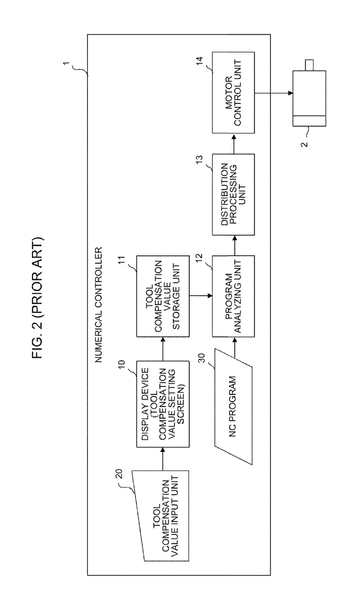
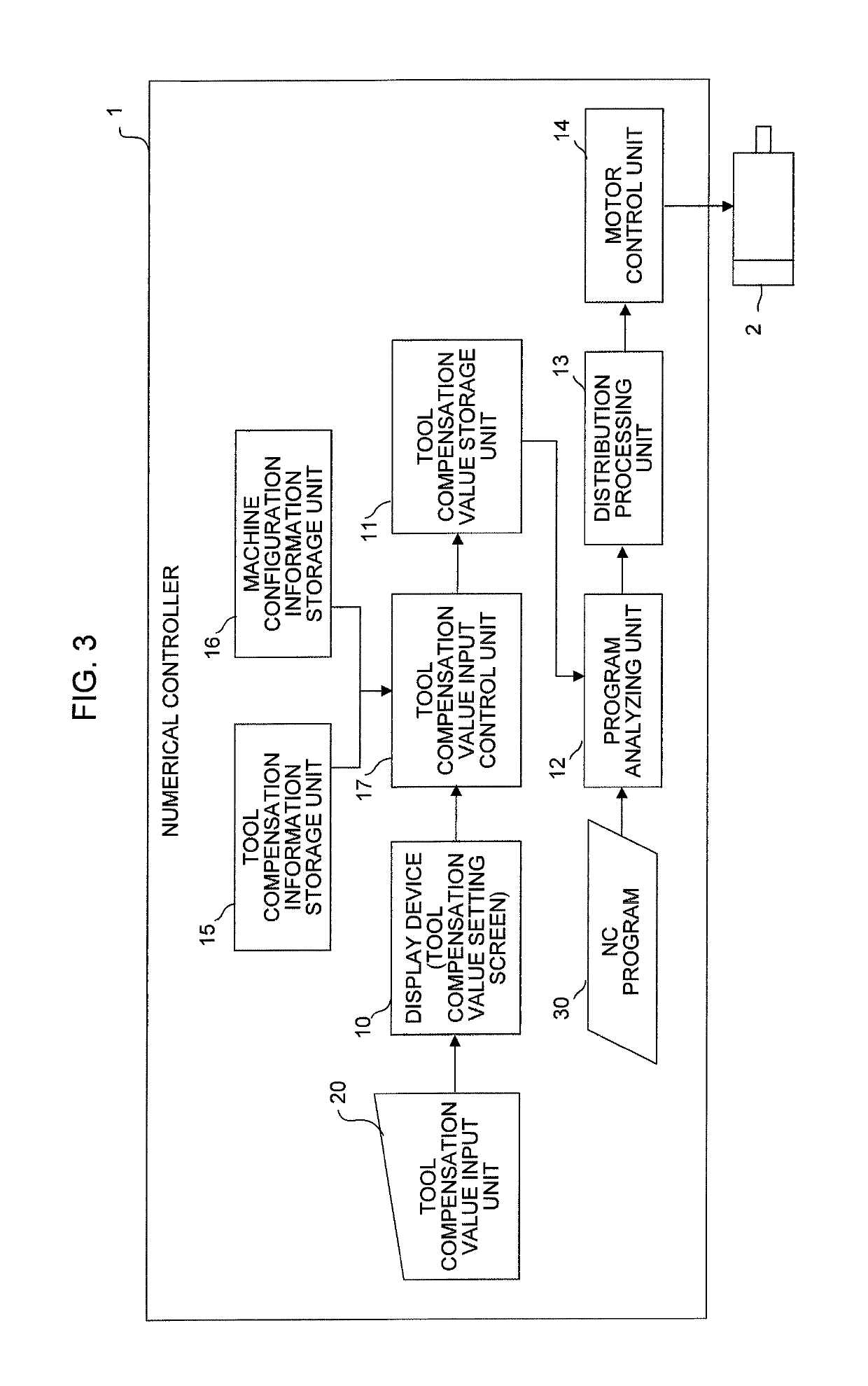
[0032]An embodiment of the present invention will be described with reference to the drawings. Components that are the same as or similar to those of a conventional technique will be described with the same reference numerals.

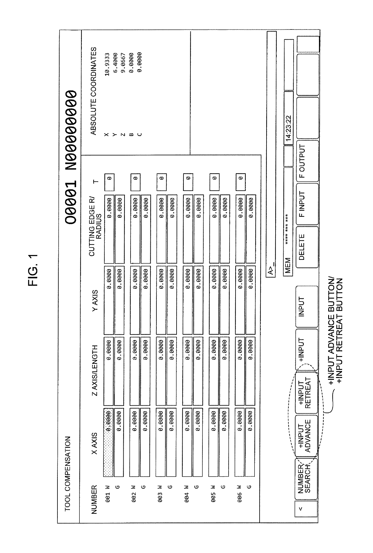
[0033]In the present invention, as shown in FIG. 1, a tool compensation value setting error is prevented, and the problem of the conventional technique described before is solved by providing tool compensation value setting buttons, a [+INPUT ADVANCE] button and a [+INPUT RETREAT] button, which clearly show influence of a change made in the tool compensation value on a relationship between a workpiece and a tool cutting edge, that is, whether the tool cutting edge is to be close (advance) to the workpiece or to be away (retreat) from the workpiece, at the time of setting a new tool compensation value to which a value inputted on a tool compensation value setting screen (a value of difference from a tool compensation value that has already been set) is applied.

[...


PUM


Abstract

A numerical controller corrects a tool compensation value for a machine tool provided with a tool for machining a workpiece based on an NC machining program. The numerical controller makes it unnecessary for a person in charge of input to be conscious of the sign of the tool compensation value and prevents a tool compensation value input error by providing an input button for bringing a workpiece and a tool cutting edge close to each other by a specified amount (+input advance) and an input button for causing the workpiece and the tool cutting edge to be away from each other by a specified amount (+input retreat) at the time of inputting the tool compensation value.

Description

BACKGROUND OF THE INVENTION1. Field of the Invention[0001]The present invention relates to a numerical controller, and more particularly to a numerical controller that prevents a tool compensation value setting error.2. Description of the Related Art[0002]In a machine tool controlled by a numerical controller, a machined shape of a workpiece (an object to be machined) is decided by how the cutting edge of a tool is to be moved relative to the workpiece. On the other hand, what is controlled by the numerical controller is a relative positional relationship between a spindle or a table to which the workpiece is fixed and a tool holder (or a tool holder) to which the tool is fitted.[0003]Various kinds of tools according to machining types are fitted to the tool holder. Since the amount and direction of protrusion from the tool holder differs according to the tools, it is not possible to perform desired machining unless a positional relationship between a reference position of the tool ...

Claims


Application Information

Patent Timeline
Patent Type & Authority Patents(United States)
IPC IPC(8): G05B19/404
CPCG05B19/404G05B2219/45044G05B2219/39177G05B19/19G05B2219/35349
Inventor SUZUKI, MAKOTO
Owner FANUC LTD
Learn More