
Image anti-aliasing system

a technology of anti-aliasing and images, applied in image enhancement, image analysis, instruments, etc., can solve the problems of easy mistakes, inability to effectively handle aliasing in said direction, and affect accuracy

Active Publication Date: 2019-09-10
BEIJING J LOGIC SEMICON TECH CO LTD
View PDF12 Cites 2 Cited by
  • Summary
  • Abstract
  • Description
  • Claims
  • Application Information

AI Technical Summary

Benefits of technology

[0009]The present invention has the following advantageous effects:[0010](1) no direction quantization is performed, so aliasing in any direction can be handled;[0011](2) low-angle aliasing can be handled well, and the angle that can be handled may be arbitrarily close to the horizontal direction.
[0010](1) no direction quantization is performed, so aliasing in any direction can be handled;
[0011](2) low-angle aliasing can be handled well, and the angle that can be handled may be arbitrarily close to the horizontal direction.

Problems solved by technology

The first disadvantage is that the direction is usually quantified into a limited number of directions, each direction corresponding to a filter along the direction, thus for directions that fall between the quantified directions, only the nearest quantified direction can be selected for filtering, or the results of filtering along several neighboring quantified directions are combined, and the accuracy is affected.
The second disadvantage is that, when processing a low angle (i.e. an angle close to the horizontal direction) pixel whose edge direction is lower than the lowest angle among the quantified directions, aliasing occurred in said direction cannot be effectively handled.
The third disadvantage is that, when processing a low angle (i.e. an angle close to the horizontal direction) pixel, pixels used for filtering are far away from one another, so mistakes are readily occur.

Method used


Image

  • Image anti-aliasing system
  • Image anti-aliasing system
  • Image anti-aliasing system

Examples


Embodiment Construction

[0022]For the purpose of having the object, technical solutions and advantages of the present invention more apparently for those skilled in the art, the present invention will be described in further detail below in conjunction with specific embodiments and with reference to the drawings.

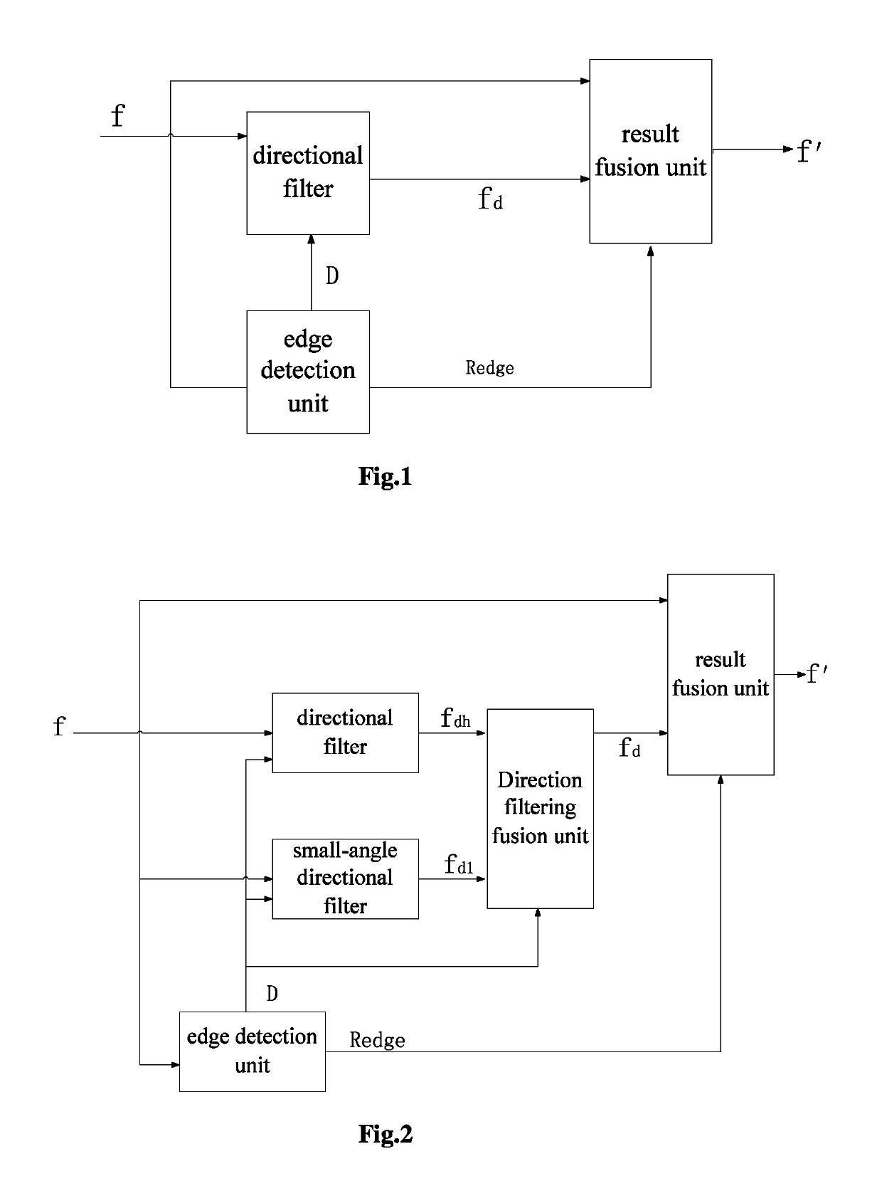
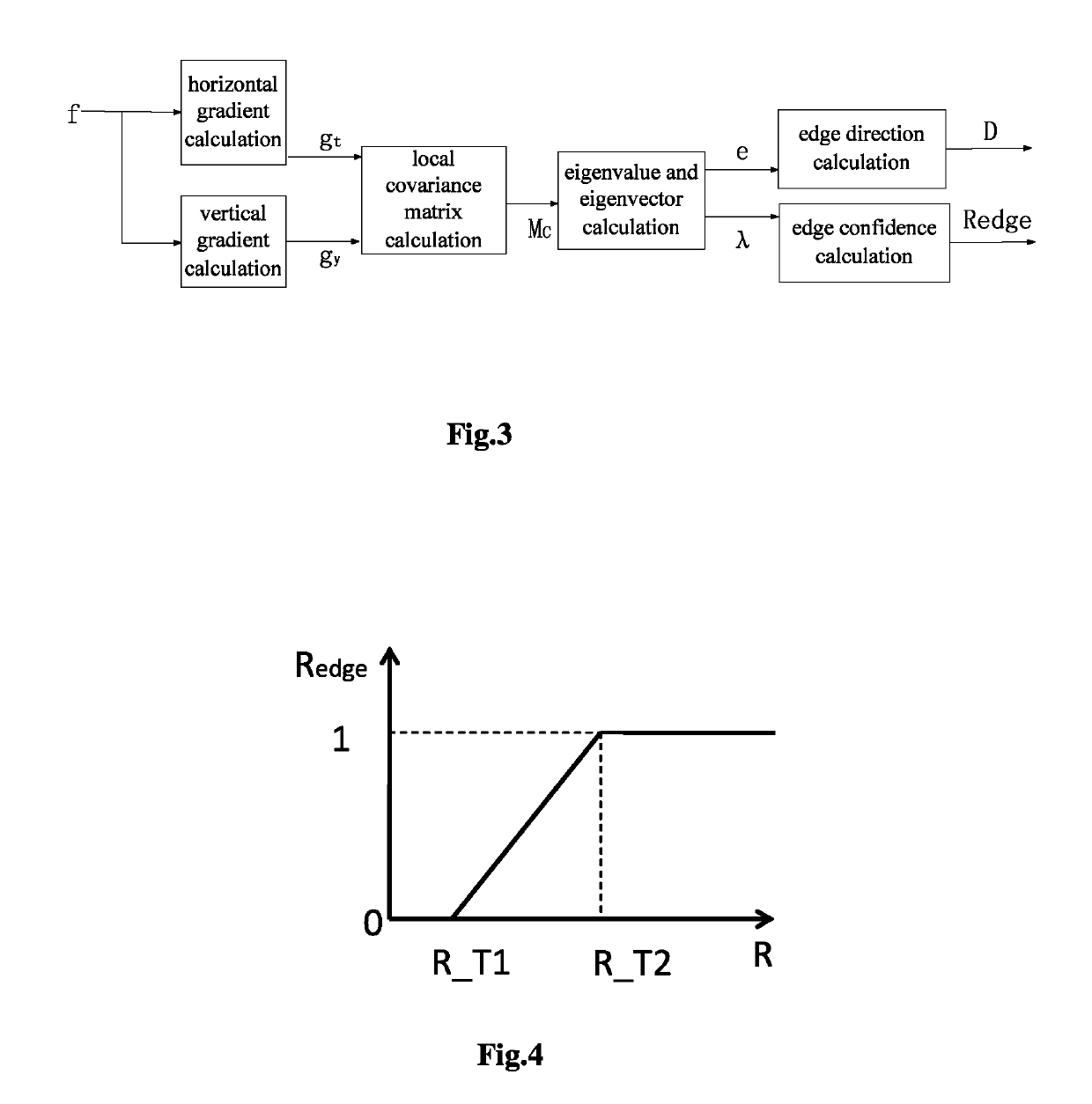
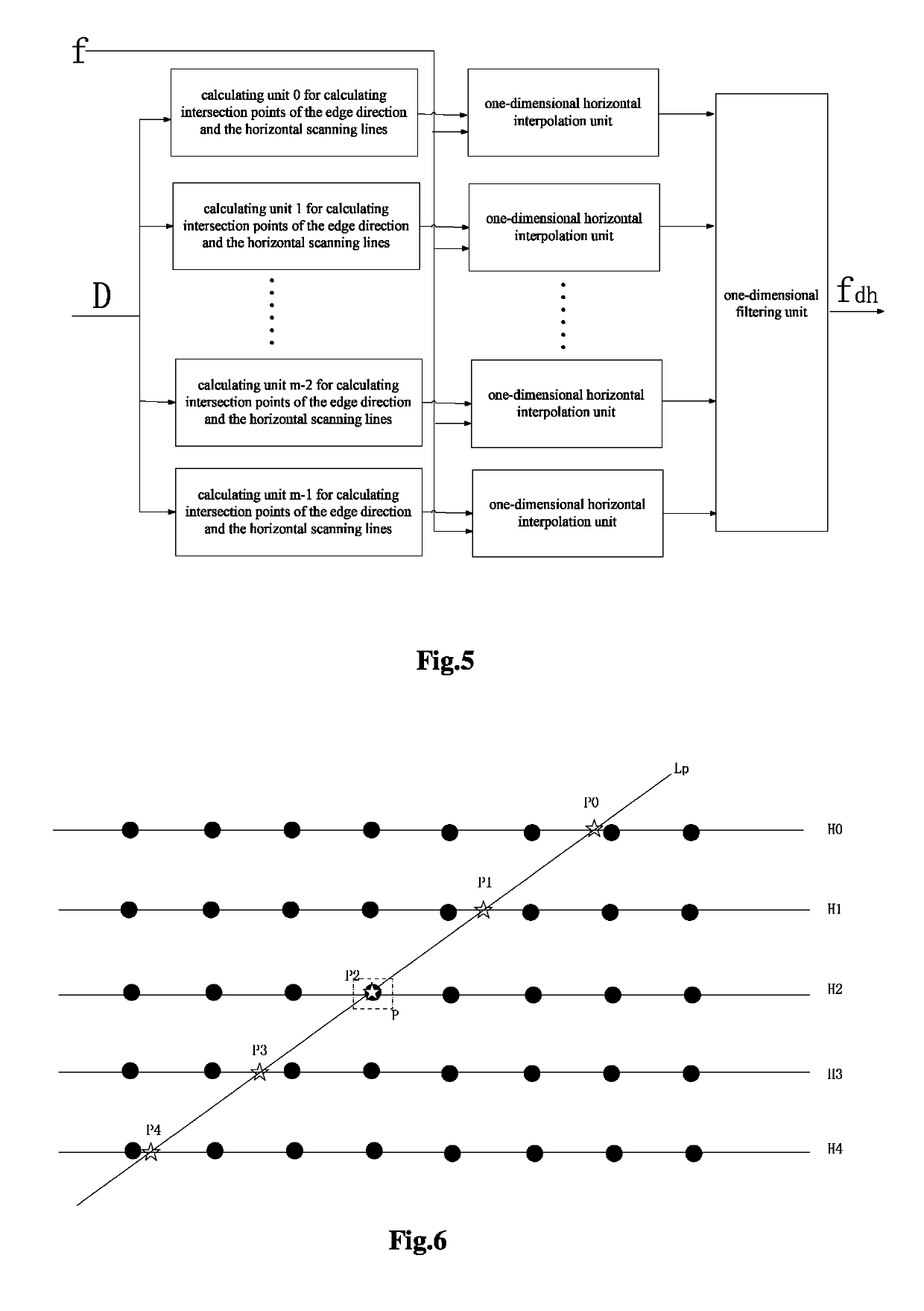
[0023]As shown in FIG. 2, the image anti-aliasing system in the present embodiment comprises an edge detection unit, a directional filter, a low-angle directional filter, a directional filtering fusion unit, and a result fusion unit. The edge detection unit outputs an edge direction D and an edge confidence Redge according to an input image f. The directional filter outputs a directional filtering result fdh based on the input image f and the edge direction D. The low-angle directional filter outputs a low-angle directional filtering result fdl based on the input image f and the edge direction D. The directional filtering fusion unit weights and combines the result fdh output from the directional f...


PUM


Abstract

The present invention discloses an image anti-aliasing system, which comprises an edge detection unit, a directional filter, a low-angle directional filter, a directional filtering fusion unit and a result fusion unit; the edge detection unit outputs the edge direction and edge confidence according to an input image, the directional filter outputs a directional filtering result based on the input image and the edge direction, the low-angle directional filter outputs a low-angle directional filtering result according to the input image and the edge direction; the directional filtering fusion unit weights and combines the result output from the directional filter and the result output from the low-angle directional filter according to the edge direction, and outputs a result of weighted combination of two directional filtering results; the result fusion unit outputs an optimized image according to the edge confidence, the input image and the result of the directional filtering fusion unit. The present invention can well handle directional filtering in any direction and it has good effect to low-angle aliasing.

Description

TECHNICAL FIELD[0001]The present invention relates to the technical field of image and video processing, in particular to the field of anti-aliasing for images, videos and graphics.BACKGROUND[0002]Processing used in image and video processing, such as scaling and de-interlacing, will bring about an aliasing effect to edges of the images, that is, in the processed image, aliasing effect or jagginess occurs near edges that look straight in the source image. In graphics rendering, when processing a straight line, aliasing will occur in the rendered straight line if mishandled. When aliasing occurs in an image, it is necessary to remove the aliasing.[0003]A conventional anti-aliasing system is as shown in FIG. 1, in which the edge of an image is detected, then a filter is selected from a group of directional filters according to the direction of the edge to perform filtering along the direction of the edge, and finally the source image and the directional filtering result are combined b...

Claims


Application Information

Patent Timeline
Patent Type & Authority Patents(United States)
IPC IPC(8): G06K9/40G06T5/00G06T7/13G06T11/60G06T5/20
CPCG06T5/002G06T5/20G06T11/60G06T7/13G06T2207/20192
Inventor GUO, RUOSHANHAN, RUITANG, RENJUN
Owner BEIJING J LOGIC SEMICON TECH CO LTD
Learn More