
High contrast electro-optic liquid crystal camera iris including liquid crystal material mixed with a dye to improve achromatic performance

a liquid crystal camera and high-contrast technology, applied in the field of liquid crystal iris, can solve the problems of unsatisfactory use as a camera iris, complex device, and inability to meet the requirements of many miniature camera applications, and achieve the effect of maximum light transmission, zero transmittance, and maximum throughpu

Active Publication Date: 2019-09-03
LC TEC DISPLAY
View PDF28 Cites 9 Cited by
  • Summary
  • Abstract
  • Description
  • Claims
  • Application Information

AI Technical Summary

Benefits of technology

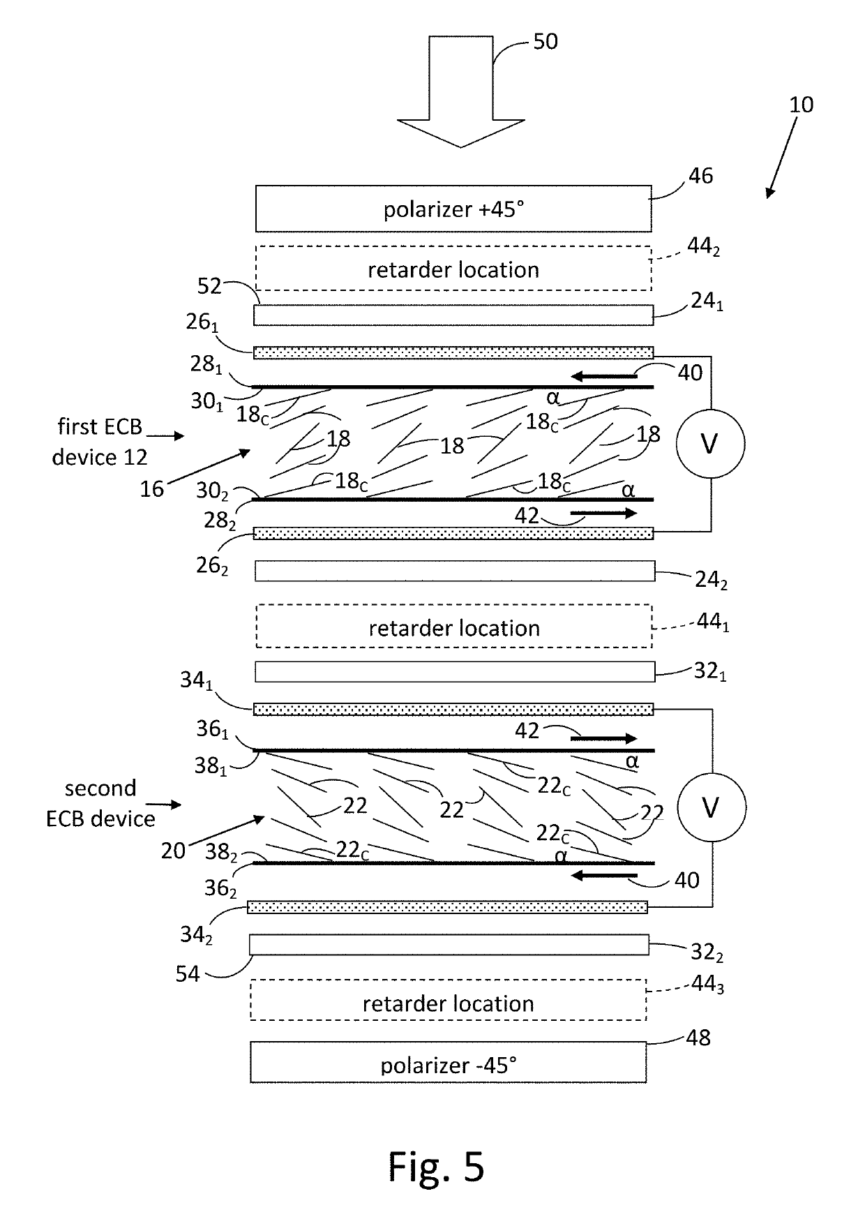
The present invention provides a dual-cell liquid crystal iris that reduces angular variation of intermediate transmittances compared with prior art liquid crystal irises. The arrangement of the first and second liquid crystal devices ensures that the light exiting the first liquid crystal device is not circularly polarized, while the light exiting the second liquid crystal device is linearly polarized in the same direction as the input linear polarization direction. The arrangement also ensures maximum throughput and a high contrast ratio when no voltage is applied to the first and second liquid crystal devices, while obtaining intermediate gray levels by applying voltages intermediate between 0V and the high drive voltage.

Problems solved by technology

The mechanical iris is complex device that is ill-suited for many miniature camera applications, such as those found in smart phones and other hand-held devices.
Prior art liquid crystal iris designs do not satisfy these requirements, which shortcomings are reasons why liquid crystal irises have not yet found widespread commercial application.
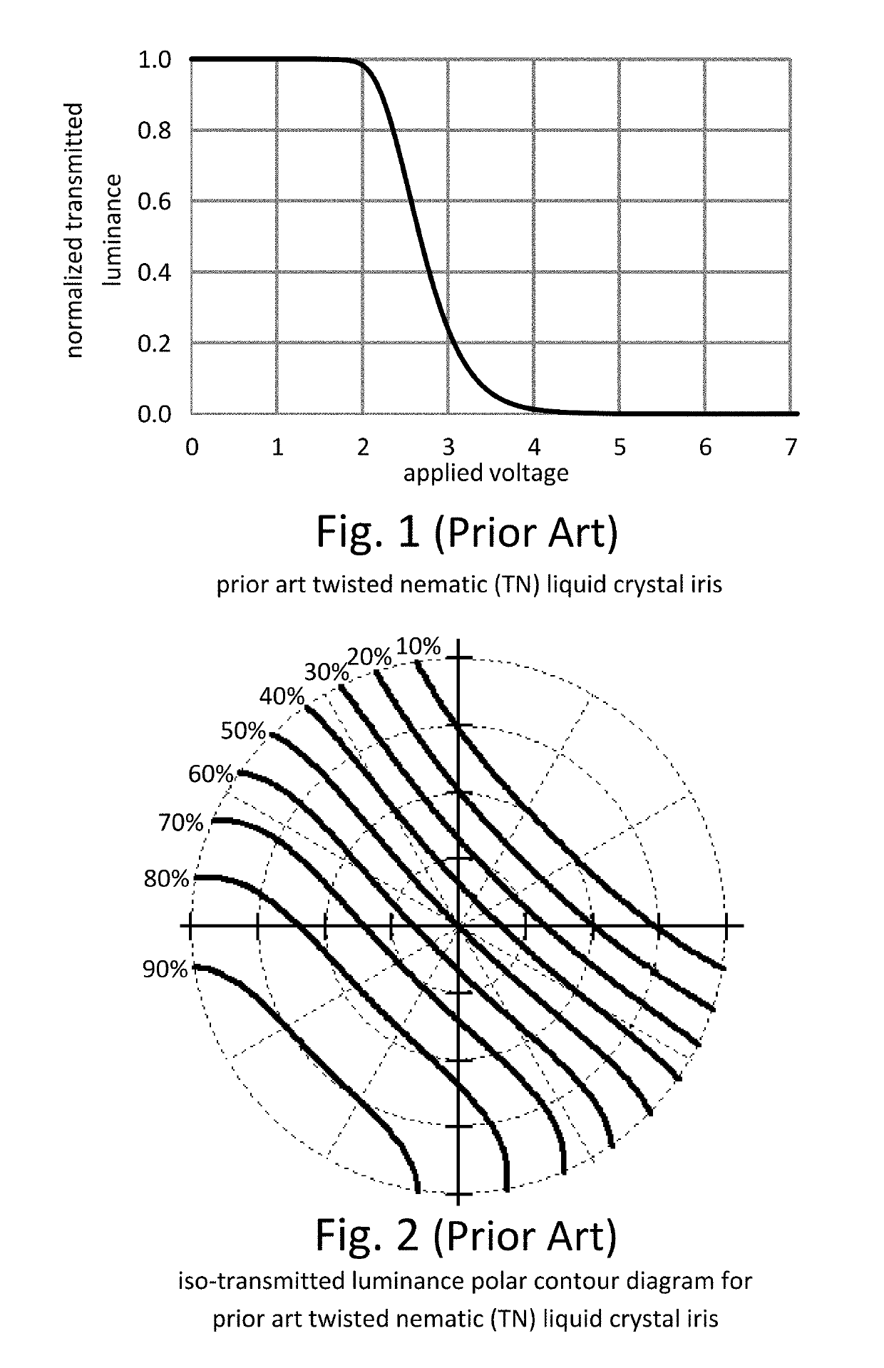
Although this TN device can achieve a high contrast ratio, the strong angular variation of intermediate transmittances of this TN device makes it unsatisfactory for use as a camera iris.
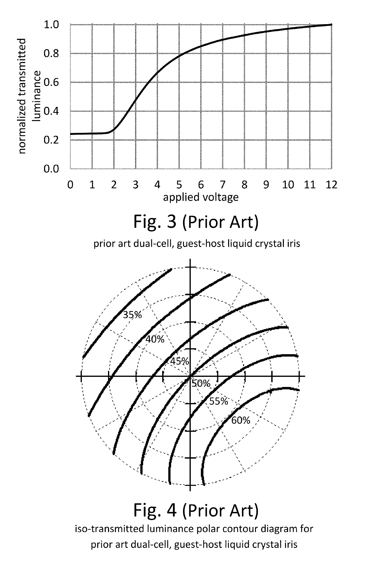
In FIG. 4, the normalized transmitted luminance varies from about 42% to 60% over a range of incident angles extending out to polar angles of 20°. FIG. 4 exhibits somewhat less angular variation of intermediate transmittances compared with the angular variation of the TN iris simulated in FIG. 2, but the low contrast ratio of the dual-cell guest-host iris makes it unsatisfactory for use as a camera iris.

Method used


Image

  • High contrast electro-optic liquid crystal camera iris including liquid crystal material mixed with a dye to improve achromatic performance
  • High contrast electro-optic liquid crystal camera iris including liquid crystal material mixed with a dye to improve achromatic performance
  • High contrast electro-optic liquid crystal camera iris including liquid crystal material mixed with a dye to improve achromatic performance

Examples


first embodiment

[0041]FIG. 5 is a simplified diagram of a liquid crystal iris 10 configured as a first implementation of the disclosed electro-optic liquid crystal camera iris. Liquid crystal iris 10 comprises a first ECB liquid crystal device 12 and a second ECB liquid crystal device 14, each of which contains liquid crystal having a positive dielectric anisotropy. For simplicity, index matching coatings of each of ECB liquid crystal devices 12 and 14 are omitted from the diagram. ECB liquid crystal devices 12 and 14 have, respectively, a director field 16 composed of liquid crystal directors 18 and a director field 20 composed of liquid crystal directors 22. Each of director fields 16 and 20 is shown in FIG. 5 at an intermediate drive voltage, V. Director field 20 of ECB liquid crystal device 14 is a mirror image of director field 16 of ECB liquid crystal device 12. In other words, liquid crystal directors 22 in director field 20 are reversely arranged in comparison to corresponding liquid crysta...

second embodiment

[0068]FIG. 21 shows the viewing angle dependence of the normalized transmitted luminance under application of a drive voltage of 2.61V, which produces 50% normalized transmitted luminance at normal incidence. These data are presented in FIG. 21 in the form of a normalized iso-transmitted luminance polar contour diagram. Comparing FIG. 21 with FIG. 2 for the prior art TN iris, it is apparent that there is remarkably less angular variation in transmitted luminance. The liquid crystal iris of the second embodiment is eminently suitable for use as a camera iris because it can achieve a high contrast ratio and exhibits capability to maintain a uniform gray level over a wide range of light input angles.

[0069]FIG. 22 shows a simulated transmitted luminance electro-optic curve of an example of a third embodiment of the disclosed electro-optic liquid crystal camera iris. The construction of the third embodiment is the same as that of liquid crystal iris 10 shown in FIG. 5, except as describe...

third embodiment

[0070]FIG. 23 shows the viewing angle dependence of the normalized transmitted luminance under application of a drive voltage of 2.69V, which gives 50% transmitted luminance at normal incidence. These data are presented in FIG. 23 in the form of a normalized iso-transmitted luminance polar contour diagram. Comparing FIG. 23 with FIG. 2 for the prior art TN iris, it is apparent that there is remarkably improved uniformity of the angular dependence of the 50% gray level. The liquid crystal iris device of the third embodiment is eminently suitable for use as a camera iris because it can achieve a high contrast ratio and exhibits capability to maintain a uniform gray level over a wide range of light input angles.

[0071]FIG. 24 is a block diagram of an example of a camera module 60 that includes the liquid crystal iris of any of the three embodiments of the disclosed electro-optic liquid crystal camera iris. FIG. 24 shows liquid crystal iris 10 of the first embodiment for purposes of conv...


PUM

PropertyMeasurementUnit
twist anglesaaaaaaaaaa
angleaaaaaaaaaa

Abstract

A high-contrast electro-optic liquid crystal camera iris provides angle independent transmission for uniform gray shades. The liquid crystal iris comprises a combination of first and second liquid crystal devices arranged in optical series and positioned between optical polarizers. The director field of the second liquid crystal device is a mirror image of the director field of the first liquid crystal device, and the first and second liquid crystal devices are placed together so that the azimuthal directions of the surface-contacting directors are in parallel alignment at the adjoining or confronting surfaces of the substrates of the first and second liquid crystal devices. The liquid crystal iris provides, therefore, less angular variation of intermediate transmittances compared with that provided by prior art liquid crystal irises.

Description

RELATED APPLICATIONS[0001]This is a division of U.S. patent application Ser. No. 15 / 024,303, filed Mar. 24, 2016, now U.S. patent Ser. No. 10 / 012,884, which is a 371 of International Application No. PCT / US2014 / 056553, filed Sep. 19, 2014, which claims benefit of U.S. Provisional Patent Application No. 61 / 976,408, filed Apr. 7, 2014, and is a continuation-in-part of U.S. patent application Ser. No. 14 / 034,283, filed Sep. 23, 2013, now U.S. Pat. No. 8,891,042.COPYRIGHT NOTICE[0002]© 2018 LC-TEC Displays AB. A portion of the disclosure of this patent document contains material that is subject to copyright protection. The copyright owner has no objection to the facsimile reproduction by anyone of the patent document or the patent disclosure, as it appears in the Patent and Trademark Office patent file or records, but otherwise reserves all copyright rights whatsoever. 37 CFR § 1.71(d).TECHNICAL FIELD[0003]This disclosure relates to a liquid crystal iris for an image recording device suc...

Claims


Application Information

Patent Timeline
Patent Type & Authority Patents(United States)
IPC IPC(8): G02B5/00G02F1/1337G02B13/00G02F1/1343H04N5/225G03B9/02G02F1/1335H04N5/238G02F1/139G02F1/1347G03B7/095G02F1/29H04N23/75
CPCH04N5/238G03B7/095G03B9/02G02B13/0075G02B5/005G02F1/133528G02F1/1337G02F1/13475H04N5/2254G02F1/13471G02F1/134309G02F1/1393G02F2001/133531G02F2001/294G02F1/133531G02F1/294H04N23/55H04N23/75
Inventor OSTERMAN, JESPERSCHEFFER, TERRY J.
Owner LC TEC DISPLAY
Learn More