
Lighting control for chilled beam

a technology of chilled beams and light sources, applied in the direction of lighting and heating equipment, heating types, ducting arrangements, etc., can solve the problem of condensation dripping on people under the chilled beams

Active Publication Date: 2019-09-03
AIR DISTRIBUTION TECH IP LLC
View PDF18 Cites 1 Cited by
  • Summary
  • Abstract
  • Description
  • Claims
  • Application Information

AI Technical Summary

Benefits of technology

The solution effectively controls air flow and temperature while preventing condensation and providing flexible lighting options, enhancing comfort and reducing drafts, allowing for both cooling during the day and heating at night.

Problems solved by technology

Chilled beams are typically used to provide cooled air, but can block light sources and, when exposed to low water temperatures or high humidity, generate condensation that drips on persons underneath the chilled beam.

Method used


Image

  • Lighting control for chilled beam
  • Lighting control for chilled beam
  • Lighting control for chilled beam

Examples


Embodiment Construction

[0011]In the description that follows, like parts are marked throughout the specification and drawings with the same reference numerals. The drawing figures might not be to scale and certain components can be shown in generalized or schematic form and identified by commercial designations in the interest of clarity and conciseness.

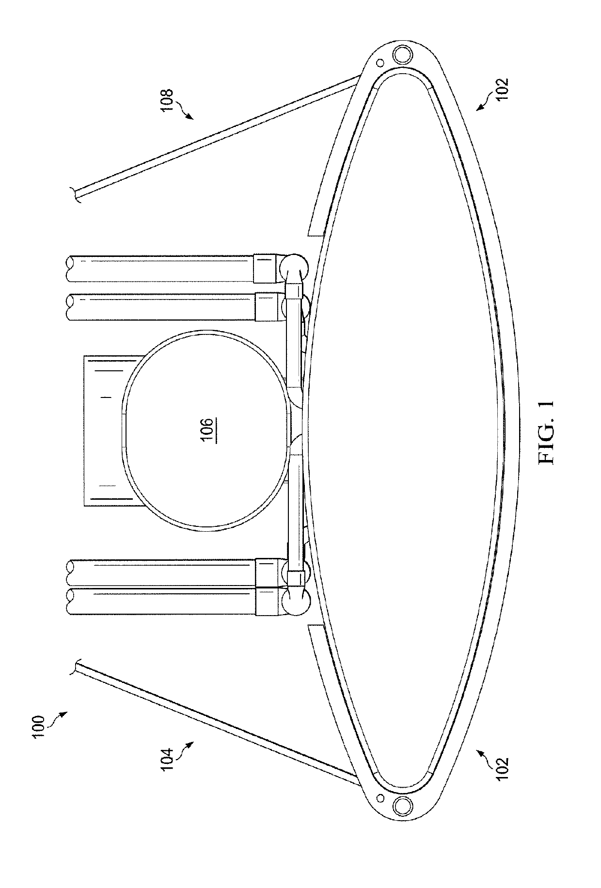
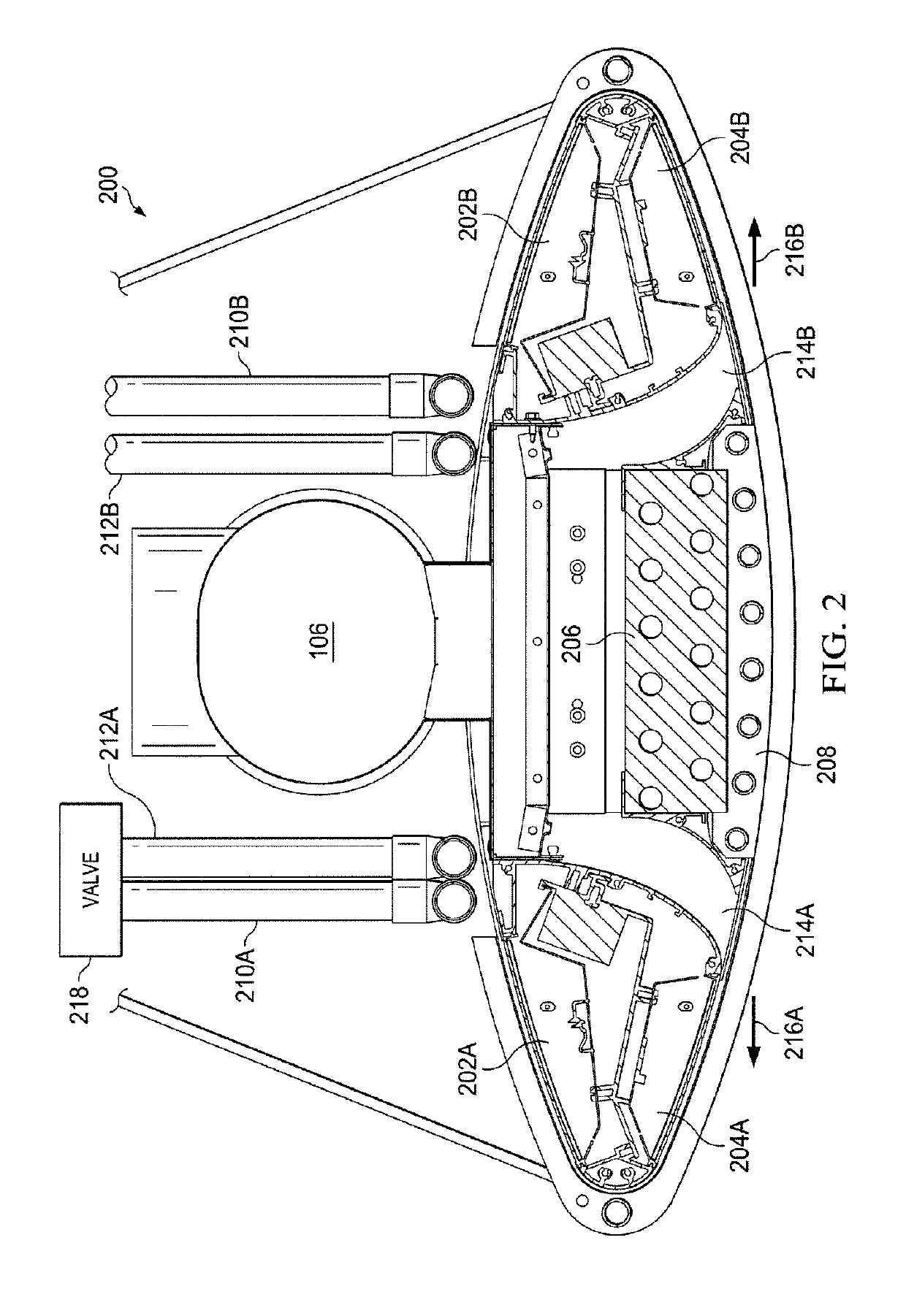
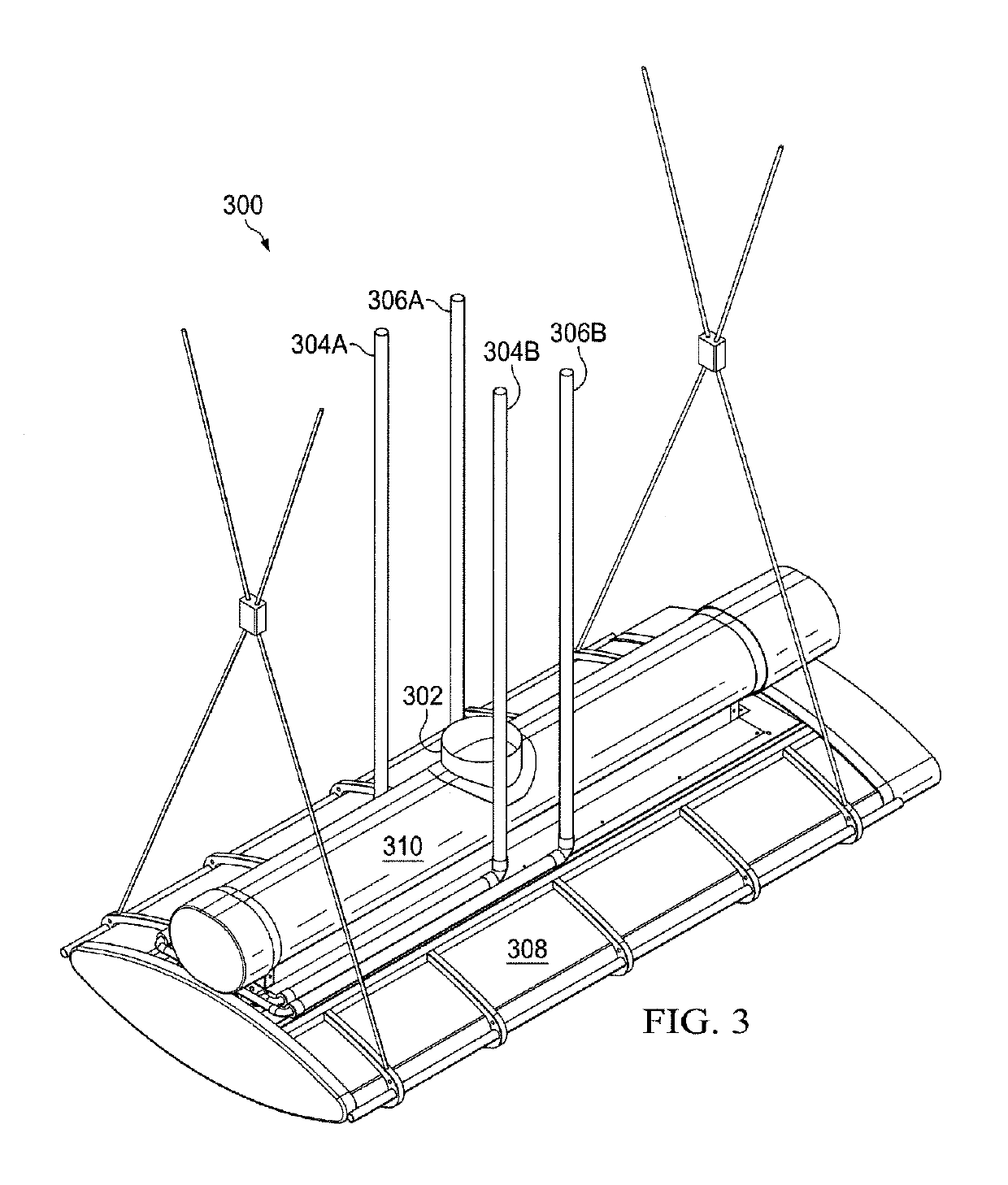
[0012]FIG. 1 is a diagram of chilled beam 100 in accordance with an exemplary embodiment of the present disclosure. Chilled beam 100 can be constructed from metallic materials such as stainless steel, copper and aluminum, can include additional decorative and functional components made from plastic, wood or other materials, and can include other suitable system components, such as lighting modules and valve controllers.

[0013]Chilled beam 100 includes fins 102, which are used to create a Coanda effect to cause conditioned air to flow out of chilled beam 100 to the left and right of chilled beam 100, instead of in a downward direction from chilled beam 100. ...


PUM


Abstract

A device comprising a fin structure, a vent disposed in the fin structure, a cooling coil disposed in the vent, a light disposed in the fin structure and wherein the fin structure is configured to create a Coanda effect for air exiting the vent.

Description

TECHNICAL FIELD[0001]The present disclosure relates generally to heating, ventilation and air conditioning (HVAC) systems, and more specifically to a chilled beam light and temperature control.BACKGROUND OF THE INVENTION[0002]Chilled beams are typically used to provide cooled air, but can block light sources and, when exposed to low water temperatures or high humidity, generate condensation that drips on persons underneath the chilled beam.SUMMARY OF THE INVENTION[0003]A chilled beam is disclosed that uses a fin structure to create a Coanda effect, to modify the flow of air from the chilled beam from a vent disposed in the fin structure. A cooling coil disposed in the vent is used to chill the air from the vent, and a light is disposed in the fin structure.[0004]Other systems, methods, features, and advantages of the present disclosure will be or become apparent to one with skill in the art upon examination of the following drawings and detailed description. It is intended that all ...

Claims


Application Information

Patent Timeline
Patent Type & Authority Patents(United States)
IPC IPC(8): F24F13/078F24F13/02F24F13/26F24F1/0059F24F1/0007F24F1/0063
CPCF24F1/00075F24F1/0059F24F13/078F24F13/0227F24F13/26F24F2221/14F24F1/0063
Inventor HIRSCH, JOACHIMZHANG, HONGHUIFREEMAN, ERNESTGLASCH, KEITH
Owner AIR DISTRIBUTION TECH IP LLC
Learn More