
Method for decoding bits in a solid state drive, and related solid state drive

a solid state drive and decoding technology, applied in the field of solid state drives, can solve the problems of relatively frequent occurrence of soft decoding failures, insatiable ssd devices, and low decoding efficiency, and achieve no area nor latency overhead, improve decoding of read bits, avoid

Active Publication Date: 2019-08-27
NANDEXT SRL
View PDF16 Cites 7 Cited by
  • Summary
  • Abstract
  • Description
  • Claims
  • Application Information

AI Technical Summary

Benefits of technology

The patent text describes a method to improve the decoding of read bits without adding any extra time or space. The method takes into account various parameters of the SSD device, such as temperature and the number of program / erase cycles, to adjust the threshold voltage distributions and reduce errors in the read operations. The technical effect of this method is to minimize the impact of soft decoding failures caused by retention errors, resulting in improved performance of the SSD device.

Problems solved by technology

The Applicant has recognized that nowadays SSD devices, especially those currently most widespread (such as the SSD devices based on MLC and TLC technologies, hereinafter referred to as MLC and TLC SSD devices) are not satisfactory.
According to the Applicant, this is substantially due to the fact that the RBER is affected by retention errors, which cause a relatively frequent occurrence of soft decoding failures (i.e. failures to decode the read bits with an acceptable UBER).
Retention errors, caused by charge leakage over time after a memory cell is programmed, are the dominant source of SSD device errors.
Indeed, as SSD device process technology scales to smaller feature sizes, the capacitance of each memory cell, and the number of electrons stored on it, decreases—for example, the known MLC memory cells can only store about 100 electrons.
This issues are exacerbated when increasing the number of bits each memory cell is capable of storing.
However, this approach burdens the computational effort of the SSD device, and particularly of its SSD controller.

Method used


Image

  • Method for decoding bits in a solid state drive, and related solid state drive
  • Method for decoding bits in a solid state drive, and related solid state drive
  • Method for decoding bits in a solid state drive, and related solid state drive

Examples


Embodiment Construction

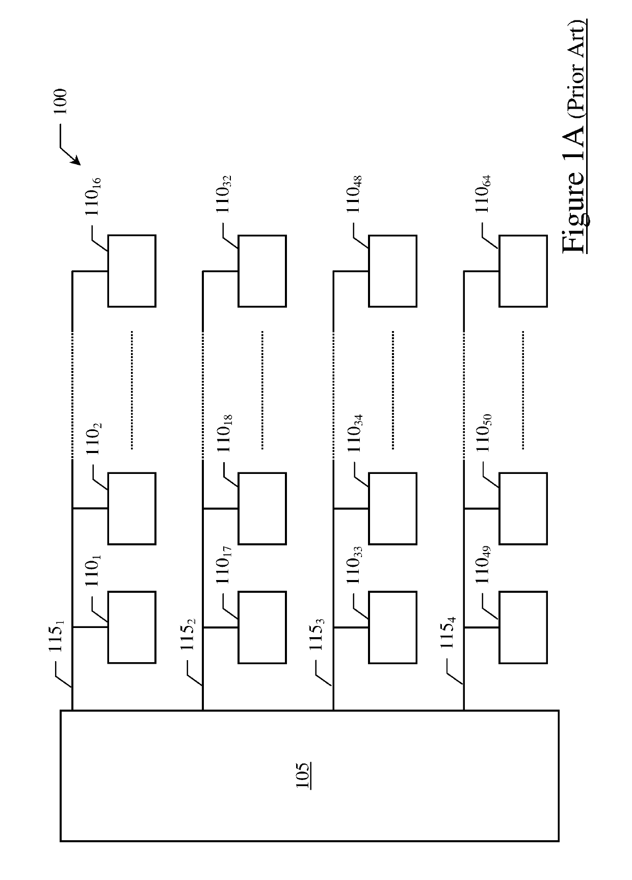
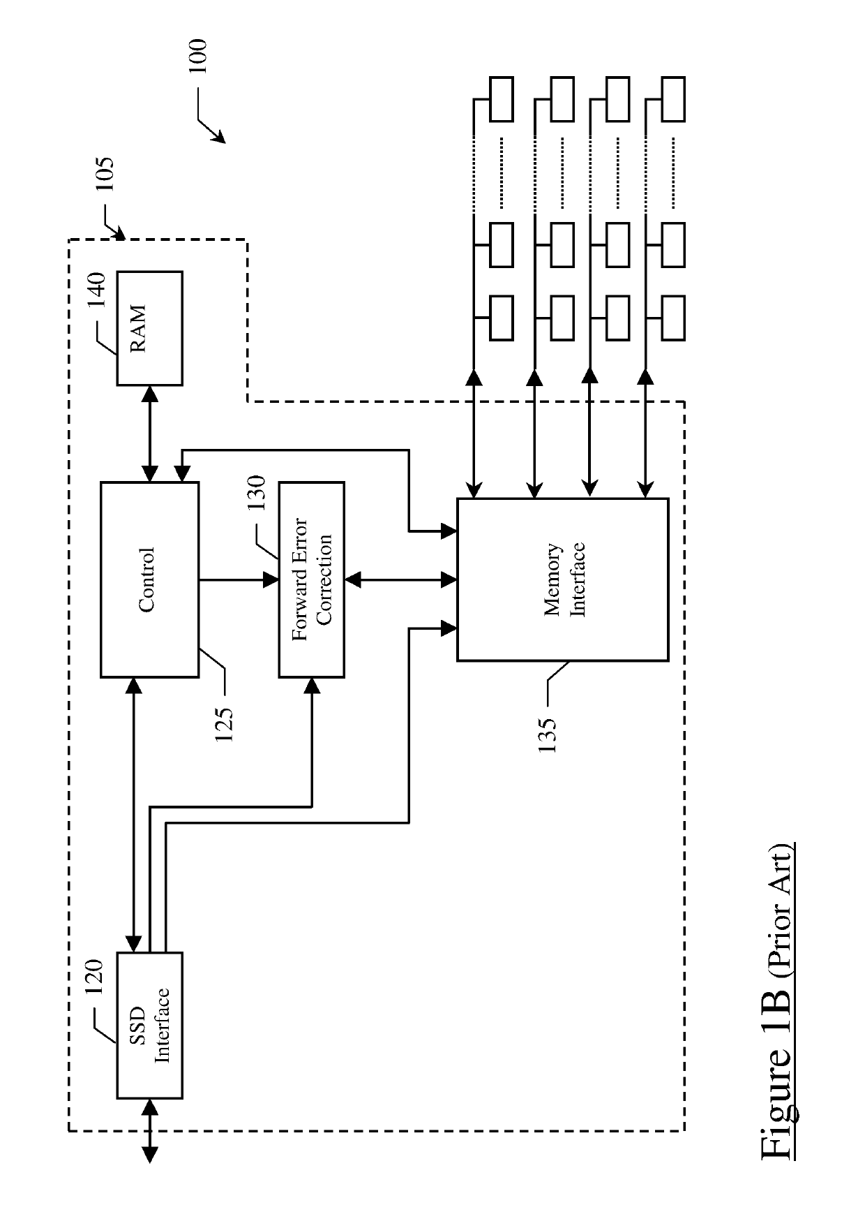
[0091]With reference to the drawings, FIG. 1A schematically shows a simplified architecture of a “Solid State Drive” device (SSD device) 100 known in the state of the art.

[0092]The SSD device 100 preferably comprises a controller (e.g., a processor and / or other control circuitry, referred to herein as SSD controller) 105, a plurality of non-volatile memory chips (e.g. flash memory chips, such as NAND flash memory chips) 110i for storing bits even in the absence of external power supply (i=1, 2, 3, . . . , I, with I=64 in the example at issue), and a plurality of (e.g., synchronous and / or asynchronous) channels 115j (j=1, 2, 3, . . . , J, with J=4 in the example at issue) communicably coupling the SSD controller 105 and the memory chips 110i to each other—in the exemplary illustration, each channel 115j communicably couples the SSD controller 105 to a set of 16 memory chips 110i (e.g., with the channels 1151, 1152, 1153 and 1154 that communicably couple the SSD controller 105 to the ...


PUM


Abstract

A method is proposed for decoding read bits including information bits from memory cells of a solid state drive. The method comprises determining a reliability indication indicative of a reliability of the read bits, and iterating the following sequence of steps:soft decoding the read bits based on said reliability indication in order to obtain said information bits,determining at least one among a time indication indicative of a time elapsed since a last writing of the memory cells and a temperature indication indicative of a temperature of the memory cells, andapplying at least one among said time indication and said temperature indication to said reliability indication.A corresponding solid state drive is also proposed.

Description

BACKGROUND OF THE INVENTION[0001]Field of the Invention[0002]The present invention generally relates to “Solid State Drives” (hereinafter, SSD devices), such as SSD devices provided with non-volatile memory chips (e.g., NAND flash memory chips) for storing data. More particularly, the present invention relates to SSD devices provided with error correction capabilities. Even more particularly, the present invention relates to a method for decoding bits in such SSD devices, and to SSD devices (or controllers thereof) implementing the method.[0003]Overview of the Related Art[0004]SSD devices are nowadays widely used, for example as storage units of computers in replacement of HDD (“Hard Disk Drives”).[0005]A common SSD device comprises non-volatile memory chips (for example, NAND flash memory chips) each one including non-volatile memory cells for storing data (bits) even in the absence of external power supply, and a SSD device controller (hereinafter, SSD controller) for managing SSD...

Claims


Application Information

Patent Timeline
Patent Type & Authority Patents(United States)
IPC IPC(8): H03M13/45G11C29/52G11C11/56G06F11/10H03M13/11H03M13/37H03M13/00G11C29/04
CPCG06F11/1012H03M13/1105H03M13/1108H03M13/1111H03M13/3707H03M13/3723H03M13/458H03M13/6325G11C2029/0409G11C2029/0411G11C7/04G11C16/349G11C2211/5644G11C11/5642G11C29/52G11C11/5628
Inventor MAFFEIS, MARGHERITA
Owner NANDEXT SRL
Learn More