
Display panel utilizing sub-pixel rendering technology

a technology of sub-pixels and display panels, applied in static indicating devices, instruments, non-linear optics, etc., can solve the problems of occupying a certain layout area, affecting the display effect, so as to achieve favorable display effects, improve abnormal display, and high resolution

Active Publication Date: 2019-08-27
NOVATEK MICROELECTRONICS CORP
View PDF20 Cites 0 Cited by
  • Summary
  • Abstract
  • Description
  • Claims
  • Application Information

AI Technical Summary

Benefits of technology

The invention provides a display panel that solves the problem of abnormal display due to excessive brightness enhancement. It achieves high resolution and favorable display effects by adaptively arranging the distribution of white sub-pixels to adjust the increase of brightness of each part of the image. The use of white sub-pixels helps to enhance display brightness and avoid abnormal display.

Problems solved by technology

As the resolution of display panel increases, however, panel manufacturers may encounter the following issues.
For example, due to the complexity of advanced pixel circuit, the number of thin film transistors in the layout may increase and occupy a certain layout area.
For this reason, it is difficult to achieve high-resolution image display with the limited layout area.
Furthermore, considering the fabrication conditions, whether the displays can achieve high resolution is also affected by the different design rules used in the fabrication of the displays or limited by the minimum safety distance of the fine metal mask.
Thus, it is necessary to increase the brightness of the backlight source to cope with the reduction of the aperture ratio, but it would increase power consumption instead.
However, the white sub-pixels in the traditional RGBW display panel can only improve the transmittance of grayscale regions (e.g. the edge of an object in the image) in the image and cannot enhance the brightness of regions of pure colors (red, green, and blue).
Therefore, the brightness of each part of the image may be enhanced inconsistently and result in poor display quality.
For the object in the displayed image, when the brightness of the edge is enhanced excessively, abnormal display problems, such as white border near the edge, may also occur.

Method used


Image

  • Display panel utilizing sub-pixel rendering technology
  • Display panel utilizing sub-pixel rendering technology
  • Display panel utilizing sub-pixel rendering technology

Examples


Embodiment Construction

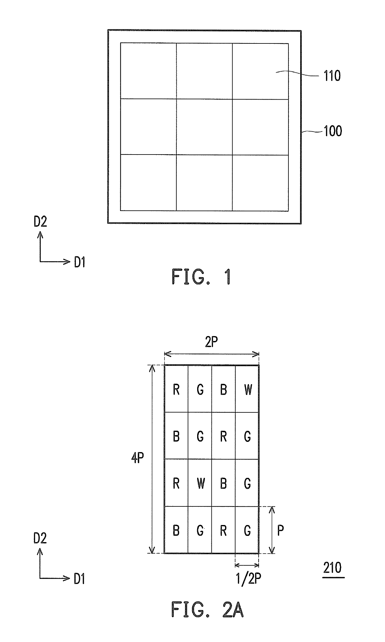
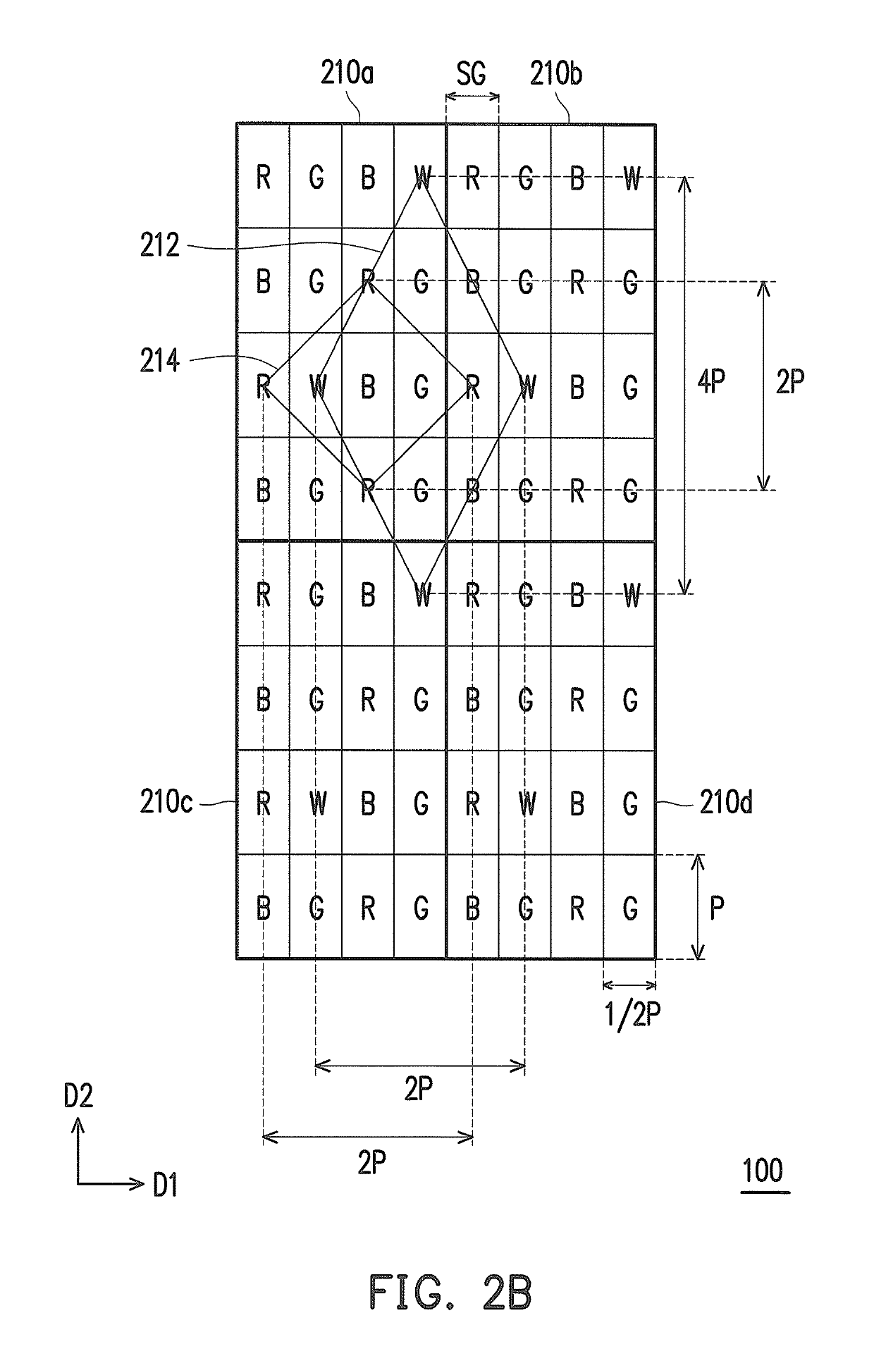
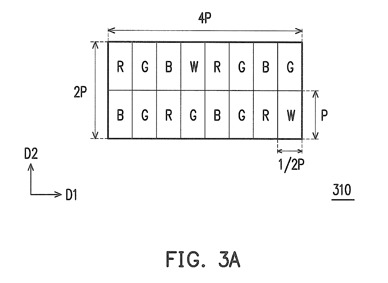
[0046]An embodiment of the invention provides a display panel, which uses white sub-pixels to enhance display brightness and adaptively adjusts configuration of the white sub-pixels on the display panel by designing an arranging frequency of the white sub-pixels in each column, such that the area of a polygon surrounded by adjacent white sub-pixels is at least twice as large as the area of a polygon surrounded by sub-pixels of other colors. In other words, the adjacent white sub-pixels may be relatively dispersed. Based on the aforementioned concept, the embodiment of the invention utilizes sub-pixel rendering (SPR) technology in combination with different arrangements and designs of sub-pixels to improve abnormal display problems, such as white border that may occur on the edge of an object in the displayed image, thereby achieving a design that is applicable to high resolution and has favorable display effects.

[0047]FIG. 1 is a schematic top view of the display panel according to ...


PUM

PropertyMeasurementUnit
areaaaaaaaaaaa
coloraaaaaaaaaa
colorsaaaaaaaaaa

Abstract

A display panel including a plurality of sub-pixel repeating units is provided. The sub-pixel repeating units are repeatedly arranged on the display panel. Each of the sub-pixel repeating units includes at least one first color sub-pixel and at least one second color sub-pixel. On the display panel, the adjacent first color sub-pixels form a first polygon, and the adjacent second color sub-pixels form a second polygon. The area of the first polygon is at least twice the area of the second polygon.

Description

CROSS-REFERENCE TO RELATED APPLICATION[0001]This application claims the priority benefit of Taiwan application serial no. 103146054, filed on Dec. 29, 2014. The entirety of the above-mentioned patent application is hereby incorporated by reference herein and made a part of this specification.BACKGROUND OF THE INVENTION[0002]Field of the Invention[0003]The invention relates to flat display technology and more particularly relates to a display panel that achieves favorable display effects with high resolution.[0004]Description of Related Art[0005]With the rapid development of display technology, the market shows growing demands for high resolution, high brightness, and low power consumption in tennis of the performance of display panels. As the resolution of display panel increases, however, panel manufacturers may encounter the following issues. For example, due to the complexity of advanced pixel circuit, the number of thin film transistors in the layout may increase and occupy a ce...

Claims


Application Information

Patent Timeline
Patent Type & Authority Patents(United States)
IPC IPC(8): G02F1/1335G09G3/36G09G3/20
CPCG09G3/2003G09G2300/0452G02F1/133514G02F2201/52G09G3/3607
Inventor YANG, HSUEH-YENYANG, KAI-MINPAI, FENG-TING
Owner NOVATEK MICROELECTRONICS CORP
Learn More