Electromagnetically actuatable gas valve, and method for increasing the seal of an electromagnetically actuatable gas valve

a technology of electromagnetically actuating gas valve and electromagnetic actuation, which is applied in the field of electromagnetic actuation gas valve, can solve problems such as affecting the sealing effect of gas valves, and achieve the effect of improving the sealing of gas valves

Active Publication Date: 2019-08-20
ROBERT BOSCH GMBH
View PDF7 Cites 0 Cited by
  • Summary
  • Abstract
  • Description
  • Claims
  • Application Information

AI Technical Summary

Benefits of technology

The proposed design of the gas valve avoids deformations that could compromise its sealing ability by keeping the stiffness of the valve seat and / or valve disk constant in the radial direction. This ensures that there are no sudden changes in stiffness between sealing seats. Additionally, the method of designing the radii of the webs and sealing webs allows for a match between the stiffness of the web or sealing web and the circumstances in which they are used.

Problems solved by technology

The proposed constant stiffness of the valve seat and / or of the valve disk in the radial direction counteracts deformations, which could impair the sealing effect of the gas valve.

Method used


Image

  • Electromagnetically actuatable gas valve, and method for increasing the seal of an electromagnetically actuatable gas valve
  • Electromagnetically actuatable gas valve, and method for increasing the seal of an electromagnetically actuatable gas valve
  • Electromagnetically actuatable gas valve, and method for increasing the seal of an electromagnetically actuatable gas valve

Examples


Embodiment Construction

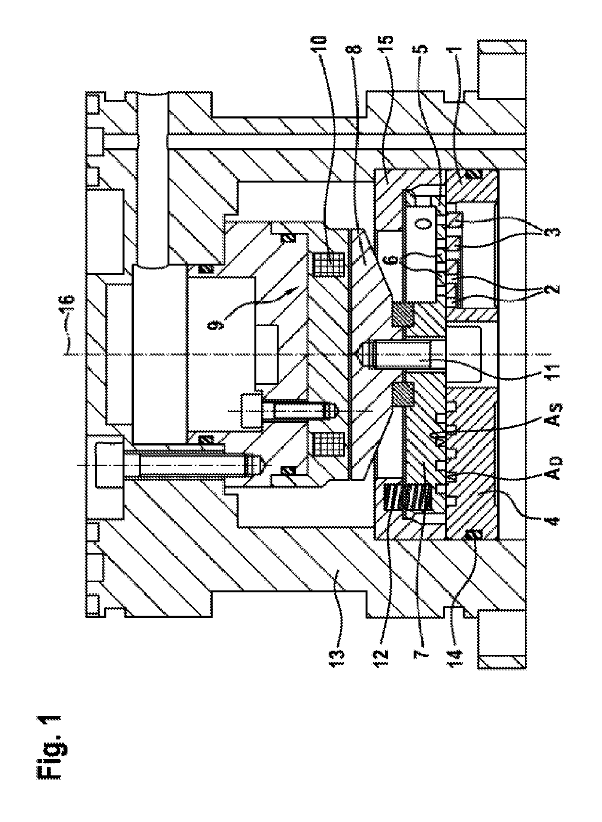
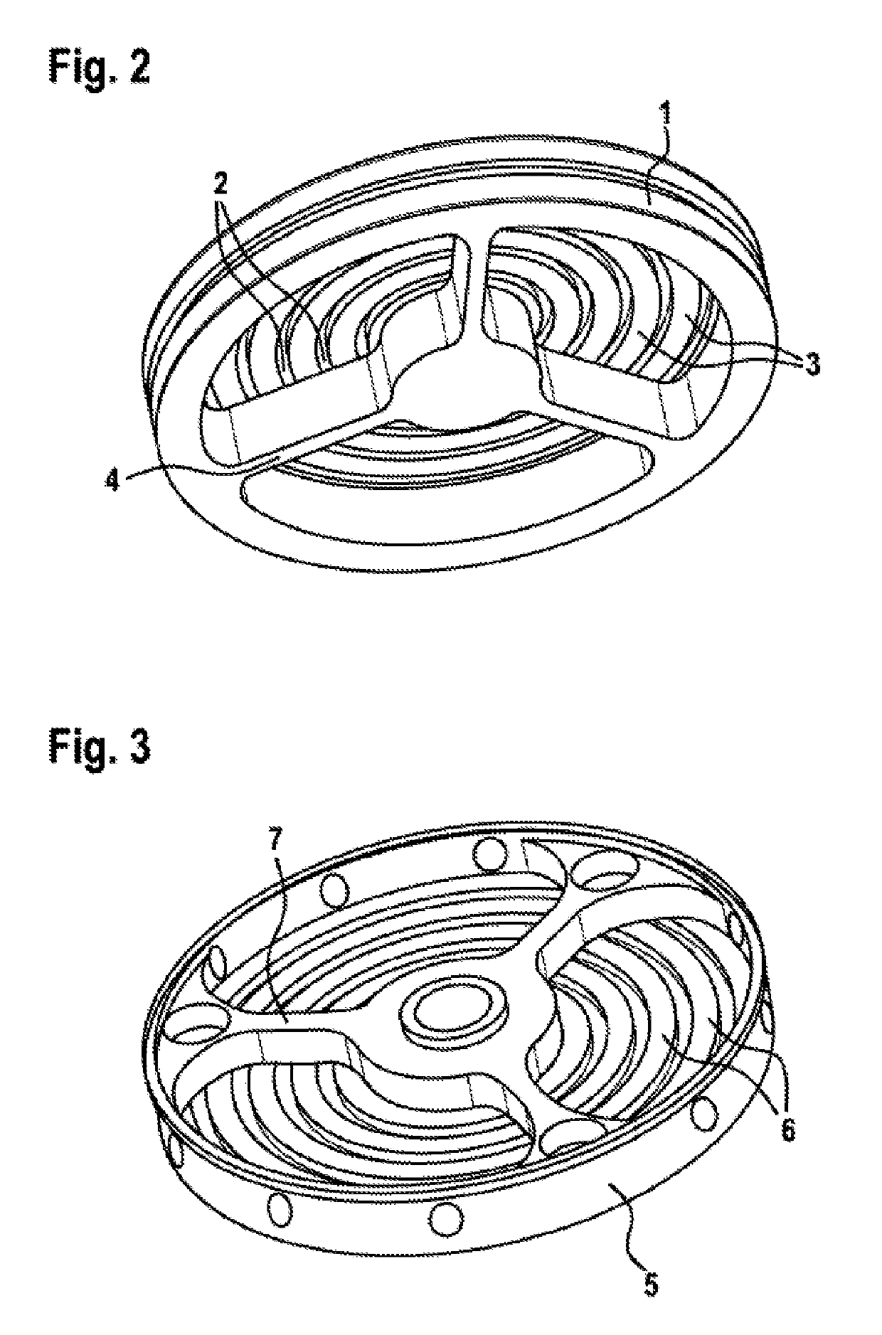
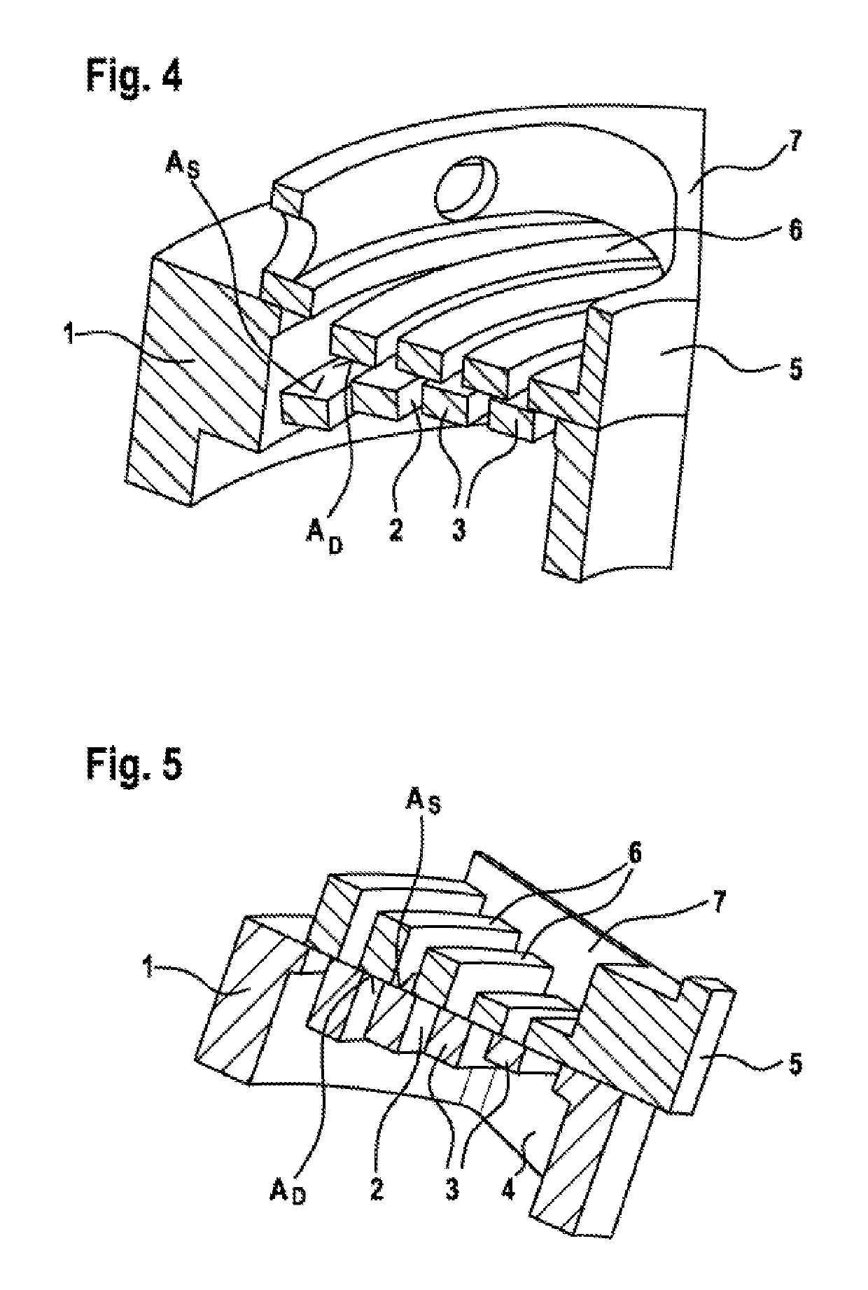
[0034]The gas valve illustrated in longitudinal section in FIG. 1 has a valve housing 13, in which a plate-shaped body is inserted to form a valve seat 1. The valve seat 1 is formed by a plurality of concentrically arranged annular webs 3, which are connected by radially extending webs 4 in such a way that partially circular through-flow openings 2 are formed between the webs 3 and 4. In this way, each web 3 forms a sealing seat with a seat surface AS, which interacts sealingly with a sealing surface AD of an annular sealing web 6 of a valve disk 5 accommodated movably in the valve housing 13 when the gas valve closes and the plurality of concentrically arranged annular sealing webs 6 of the valve disk 5 are each brought into overlap with a partially circular through-flow opening 2 of the valve seat 1.

[0035]A magnet subassembly 9 having a magnet coil 10 for actuating the gas valve is furthermore accommodated in the valve housing 13. Here, the magnet subassembly 9 interacts with an a...


PUM


Abstract

The invention relates to an electromagnetically actuatable gas valve for metering a gaseous fuel into a suction tract of a motor, in particular a gas or diesel gas motor, comprising a valve seat (1) which is designed as a flat seat and which has multiple annular webs (3) that are arranged in a concentric manner and are connected via at least one radially running web (4) in order to delimit circular or semicircular through-flow openings (2). The electromagnetically actuatable gas valve further comprises a movable valve plate (5) which sealingly interacts with the valve seat (1) and which has multiple annular sealing webs (6) that are arranged in a concentric manner and can be brought into an overlapping arrangement with the circular or semicircular through-flow openings (2) of the valve seat (1). According to the invention, the rigidity of the valve seat (1) and / or the valve plate (5) is substantially constant in the radial direction, the rigidity of the valve seat (1) being greater than the rigidity of the valve plate (5). The invention further relates to a method for increasing the seal of an electromagnetically actuatable gas valve.

Description

BACKGROUND OF THE INVENTION[0001]The invention relates to an electromagnetically actuatable gas valve for metering a gaseous fuel into a suction tract of an engine, in particular a gas or diesel / gas engine. The invention furthermore relates to a method for increasing the seal of an electromagnetically actuatable gas valve.[0002]Electromagnetically actuatable gas valves for injecting gaseous fuels into a suction tract of an engine are widely known. The use of such valves can involve combining them to form a central injection unit for supplying a plurality of cylinders of the engine with gaseous fuel (central gas injection—“CGI”) or providing at least one separate gas valve for each cylinder (multi-point injection—“MPI”).[0003]A gas valve of the type in question is disclosed by German Laid-Open Application DE 199 05 721 A1, for example. In order to provide a large passage cross section combined with short switching and response times, there is a proposal in this document for a gas val...

Claims


Application Information

Patent Timeline
IPC IPC(8): F16K31/06F16K25/00F02M21/02
CPCF16K31/0655F02M21/0233F02M21/0245F02M21/0254F02M21/0257F02M21/0263F16K25/005F16K31/0658F02M21/0272Y10T137/87507Y02T10/32Y10T137/7839Y10T137/87314Y02T10/30
Inventor WINKLER, BERNDPLOECKINGER, ANDREASGERSTMAYR, JOHANNESNADER, MANFREDZEHETNER, CHRISTIAN
Owner ROBERT BOSCH GMBH
Why Eureka
Try Eureka