
Power connector

a technology of power connectors and connectors, applied in the direction of coupling contact members, coupling device connections, connections effected by permanent deformation, etc., can solve the problems of increasing manufacturing difficulty, poor difficult pressing of handle bb>112/b>, so as to increase the increase the mechanical strength and flexibility of lock assembly, the effect of easy assembly or disassembly

Active Publication Date: 2019-08-13
MOLEX INC
View PDF18 Cites 10 Cited by
  • Summary
  • Abstract
  • Description
  • Claims
  • Application Information

AI Technical Summary

Benefits of technology

The solution ensures correct terminal positioning, increased mechanical strength and flexibility of the lock assembly, and reduces manufacturing complexities like sink mark deformation.

Problems solved by technology

However in the existing power connector, the elastic arms B113 extend outwardly from the pressing handle B112 and then directly connect downwardly with the first insulative housing B1, which results in poor flexibility of the lock assembly B11, makes the pressing handle B112 difficult to press down and operate.
In addition, the latch arm B114 of the existing power connector is a piece which is entirely solid, a thickness of the latch arm B114 is large, which will increase the difficulty of manufacturing, particularly result in uneven wall thickness in the mold injection process, and result in the subsequent problem of sink mark deformation.
The lock member in the prior art is a thick solid block (for example the latch arm) or has a small opening, because the wall thickness is too thick, uneven filling occurs during injection molding and the uneven filling together with subsequent thermal expansion and contraction easily make the lock member deformed.

Method used


Image

  • Power connector
  • Power connector
  • Power connector

Examples


Embodiment Construction

[0049]The following disclosed content provides various embodiments or exemplifications used to implement various features of the present disclosure. Specific examples of elements and configurations are described as follows, so as to simplify the disclosed content of the present disclosure. Certainly, these are merely examples, and are not used to limit the present disclosure. For example, in the following description, that a first feature is formed on or above a second feature may comprise an embodiment that the first feature and the second feature are formed to directly contact with each other, may also comprise an embodiment that other feature is formed between the first feature and the second feature, therefore the first feature and the second feature do not directly contact with each other. Moreover, the present disclosure may allow a symbol and / or a character of an element to be repeated in different examples. The repetition is used for simplification and clearness, but is not ...


PUM


Abstract

The present disclosure relates to a power connector which comprises an insulative housing and a terminal. The insulative housing defines a terminal receiving groove therein and comprises a stopping wall. The terminal is positioned in the terminal receiving groove and comprises a mating portion, a stopping portion and a wire connecting portion. The stopping portion abuts against the stopping wall and comprises a first horizontal portion and a second horizontal portion. The first horizontal portion comprises a first front end edge. The second horizontal portion comprises a second front end edge. A portion of a front end of the first horizontal portion and a portion of a front end of the second horizontal portion are cut off, therefore when the terminal clamps the wire, the first front end edge and the second front end edge do not splay forwardly and outwardly to protrude forwardly, but are parallel to each other or respectively extend backwardly, which thus can avoid the first front end edge and the second front end edge of the stopping portion from abutting against the stopping wall first due to the protruding.

Description

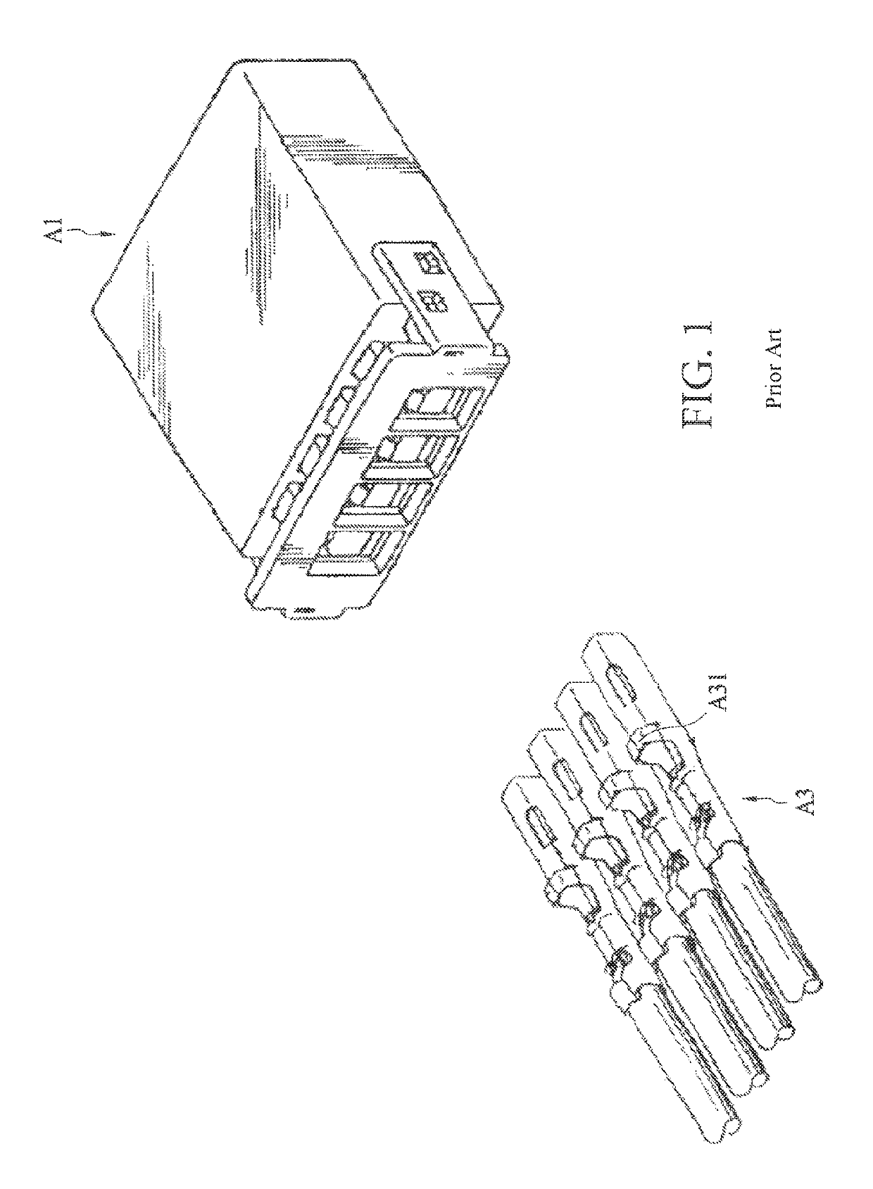
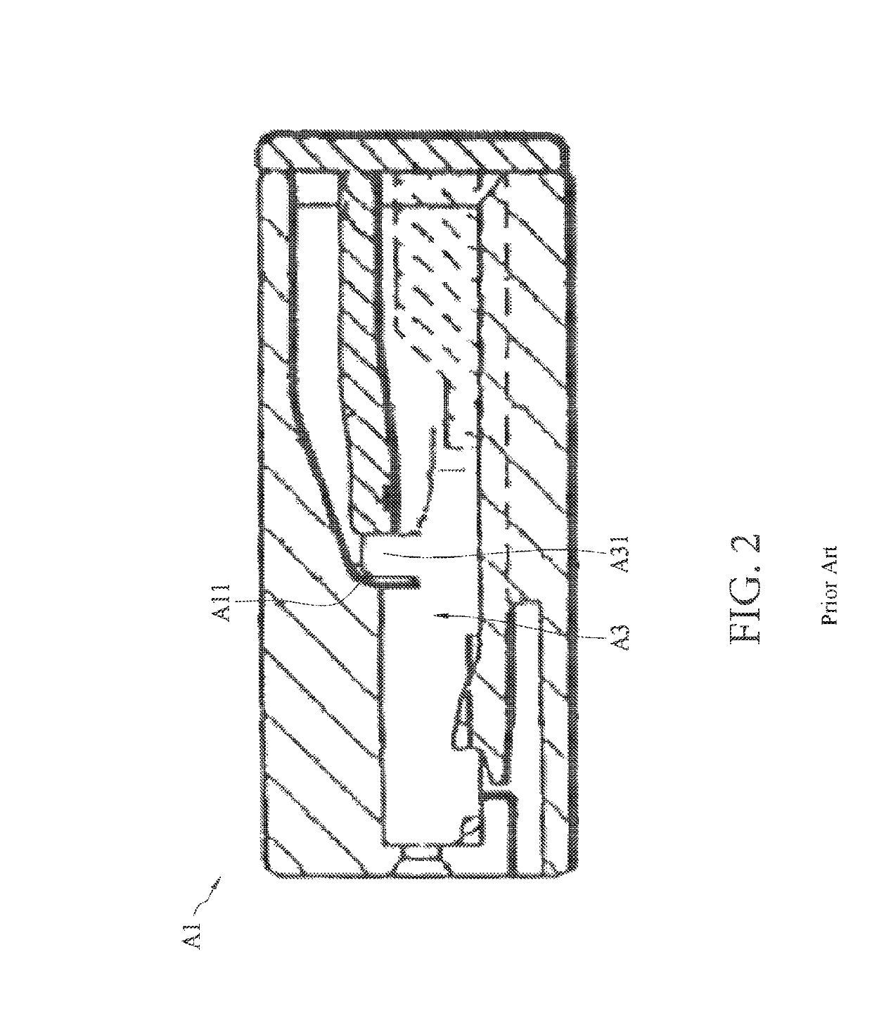
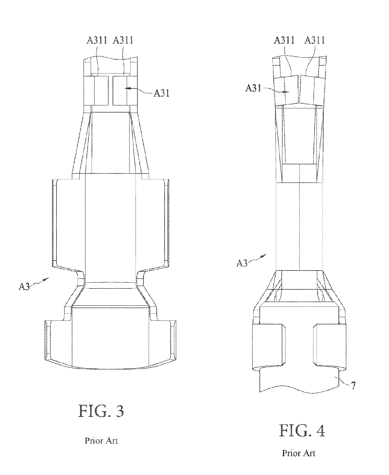
RELATED APPLICATIONS[0001]This application claims priority to Chinese Application No. 201710488295.5, filed Jun. 23, 2017, which is incorporated herein by reference in its entirety.TECHNICAL FIELD[0002]The present disclosure relates to a power connector, and particularly to a power connector comprising an insulative housing and a terminal.BACKGROUND ART[0003]A power connector has been widely used in electronic products, and comprises a terminal for connecting a wire and an insulative housing receiving the terminal.[0004]FIG. 1 is an exploded schematic view of an existing power connector, FIG. 2 is a assembled schematic view of the existing power connector of FIG. 1, which are disclosed in United States patent U.S. Pat. No. 5,458,511. Referring to FIG. 1, the existing power connector comprises an insulative housing A1 and a terminal A3, the terminal A3 comprises a stopping portion A31. Referring to FIG. 2, the insulative housing A1 comprises a stopping wall A11. When the terminal A3 ...

Claims


Application Information

Patent Timeline
Patent Type & Authority Patents(United States)
IPC IPC(8): H01R13/627H01R13/428H01R4/18H01R13/436H01R13/422H01R13/05H01R13/11
CPCH01R13/6272H01R4/185H01R13/428H01R13/4368H01R13/4223H01R13/057H01R13/114H01R13/424H01R13/40H01R13/502H01R13/629H01R13/639H01R13/24
Inventor ZHENG, YOU-XIANGYIN, HAO
Owner MOLEX INC
Learn More