
Capacitive sensor

a capacitive sensor and capacitive technology, applied in the field of capacitive sensors, can solve the problem of low tolerance of electrostatic discharge (esd) compared with the case using ito, and achieve the effect of improving esd toleran

Inactive Publication Date: 2019-08-06
ALPS ALPINE CO LTD
View PDF14 Cites 3 Cited by
  • Summary
  • Abstract
  • Description
  • Claims
  • Application Information

AI Technical Summary

Benefits of technology

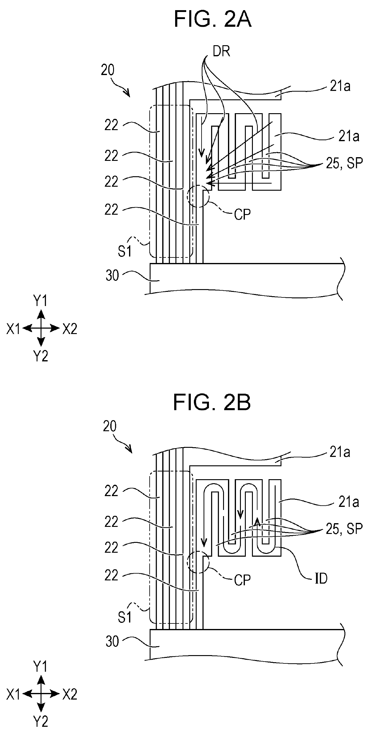
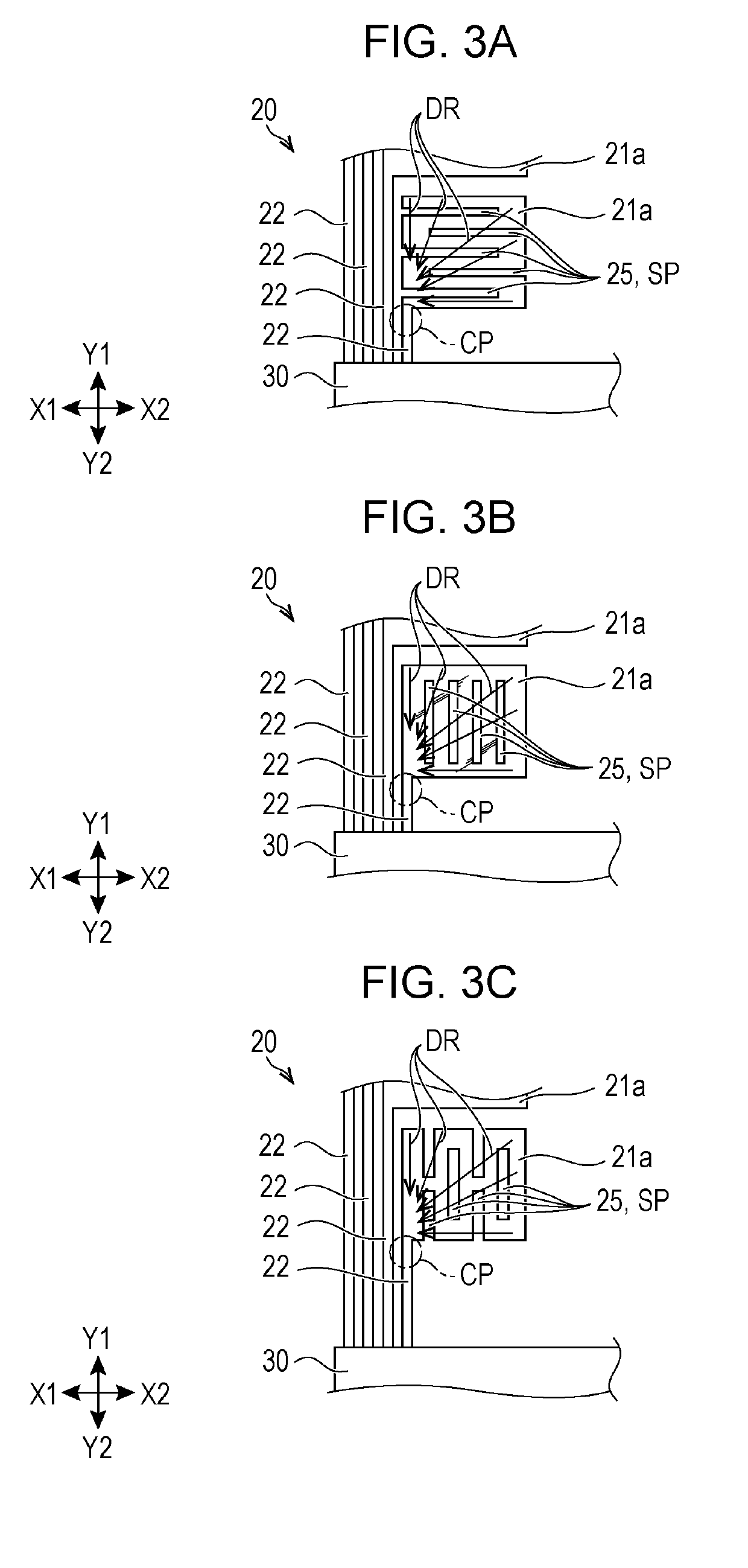
The present invention provides a capacitive sensor that can have sufficient ESD tolerance even when using a light-transmissive conductive film containing metal nanowires. The sensor has a detection pattern with a plurality of detection electrodes and current path-setting sections to prevent the current from flowing into the lead-out wiring and enhance ESD tolerance. The current path-setting sections can have slit patterns or plural slit patterns, and the current is meandered to avoid the straight line connection between the detection electrode and the lead-out wiring. The metal nanowires can be silver nanowires, which further enhance ESD tolerance.

Problems solved by technology

However, a case using metal nanowires in a light-transmissive conductive film having a monolayer structure has a problem in that the electrostatic discharge (ESD) tolerance is low compared with the case using ITO.

Method used


Image

  • Capacitive sensor
  • Capacitive sensor
  • Capacitive sensor

Examples


Embodiment Construction

[0023]Embodiments of the present invention will now be described based on the drawings. In the following descriptions, the same members are designated with the same reference numerals, and explanations of members once described are appropriately omitted.

[0024]Configuration of Capacitive Sensor

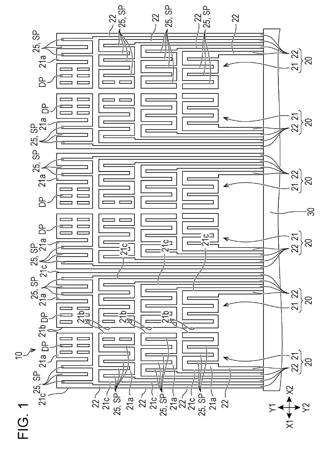
[0025]FIG. 1 is a plan view illustrating an example of the conductive pattern of a capacitive sensor according to an embodiment.

[0026]As shown in FIG. 1, the capacitive sensor according to the embodiment has a configuration in which patterns 20 of a light-transmissive conductive film having a monolayer structure are provided on a film base material as an example of a base material 10. The patterns 20 each include a detection pattern 21 and a lead-out wiring 22.

[0027]The base material 10 may be made of any material. Examples of the material of the base material 10 include inorganic substrates having light transmissivity and plastic substrates having light transmissivity. The base material 10 may...


PUM

PropertyMeasurementUnit
currentaaaaaaaaaa
diameteraaaaaaaaaa
diameteraaaaaaaaaa

Abstract

A capacitive sensor includes a base material provided with a pattern of a light-transmissive conductive film. The light-transmissive conductive film contains metal nanowires. The pattern includes a detection pattern formed of a plurality of detection electrodes arranged with intervals and a plurality of lead-out wirings linearly extending in a first direction from the corresponding ones of the plurality of the detection electrodes. At least one of the detection electrodes of the detection pattern includes a current path-setting section for elongating the linear path length of the current from the detection electrode toward the lead-out wiring.

Description

CLAIM OF PRIORITY[0001]This application is a Continuation of International Application No. PCT / JP2015 / 080503 filed on Oct. 29, 2015, which claims benefit of Japanese Patent Application No. 2015-007252 filed on Jan. 16, 2015. The entire contents of each aforementioned application is incorporated herein by reference.BACKGROUND OF THE INVENTION1. Field of the Invention[0002]The present invention relates to a capacitive sensor provided with a pattern of a light-transmissive conductive film containing metal nanowires.2. Description of the Related Art[0003]Japanese Unexamined Patent Application Publication No. 2010-191504 discloses a touch switch of a capacitive sensor including a transparent conductive film having a monolayer structure. The touch switch disclosed in Japanese Unexamined Patent Application Publication No. 2010-191504 is composed of a touch electrode section and a wiring section of a meshed metal wire extending from the touch electrode. This touch switch configuration can b...

Claims


Application Information

Patent Timeline
Patent Type & Authority Patents(United States)
IPC IPC(8): G06F3/041G02F1/1333B32B15/02G06F3/044
CPCG06F3/044B32B15/02G02F1/13338G06F3/0416G06F2203/04112B32B2307/202B32B2307/412B32B2457/208G06F3/04164G06F3/0443G06F3/0448H01B7/00
Inventor YAMAI, TOMOYUKIBITO, MITSUOKITAMURA, YASUYUKIHIRAKI, YUTAISHIBASHI, SETSUOYAZAWA, MANABU
Owner ALPS ALPINE CO LTD
Learn More