Electric machine for a motor vehicle, coil carrier for an electric machine, and motor vehicle

a technology for electric machines and coil carriers, applied in the field of electric machines, can solve the problems of inability to use conventional electric machines, efficient cooling fluids, and may now find applications, and achieve the effect of facilitating the insertion of coil carriers

Active Publication Date: 2019-07-23
AUDI AG
View PDF27 Cites 1 Cited by
  • Summary
  • Abstract
  • Description
  • Claims
  • Application Information

AI Technical Summary

Benefits of technology

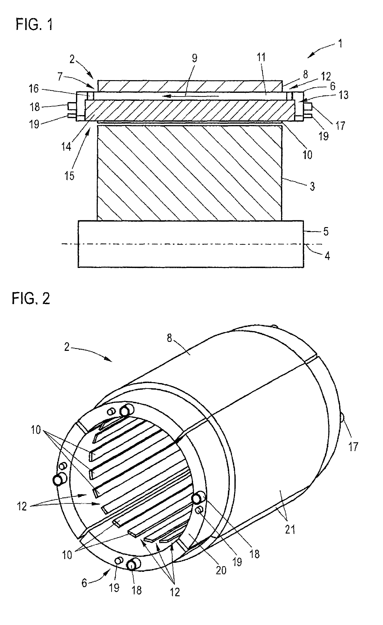
[0011]An electric machine according to the present invention can thus be used with a wide variety of cooling fluids since the fluidtight enclosure of the coil carrier prevents contact of any used cooling fluid with the stator and the rotor. As a result, any of the efficient cooling fluids, which cannot be used in conventional electric machines, may now find application.
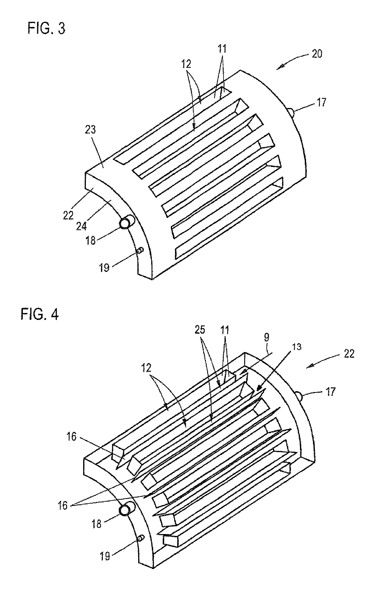
[0012]According to another advantageous feature of the present invention, the laminated core can have several teeth, with the coil carrier having through openings defined by walls and traversed by the teeth, “'Teeth” relate hereby to parts of the laminated core that project out from a stator core or stator yoke and form the slots for receiving the coil assembly. Thus, the teeth guide the magnetic flux, generated by the stator coils, in the direction of the rotor. Advantageously, the teeth are configured to extend flush with a rotor-proximal outer surface of the coil carrier, so as to avoid a widening of an air gap between the stator and the rotor. The through openings are suitably configured to complement the teeth. Advantageously, the teeth are configured to form slots with parallel flanks to facilitate insertion of the coil carrier onto the laminated core.
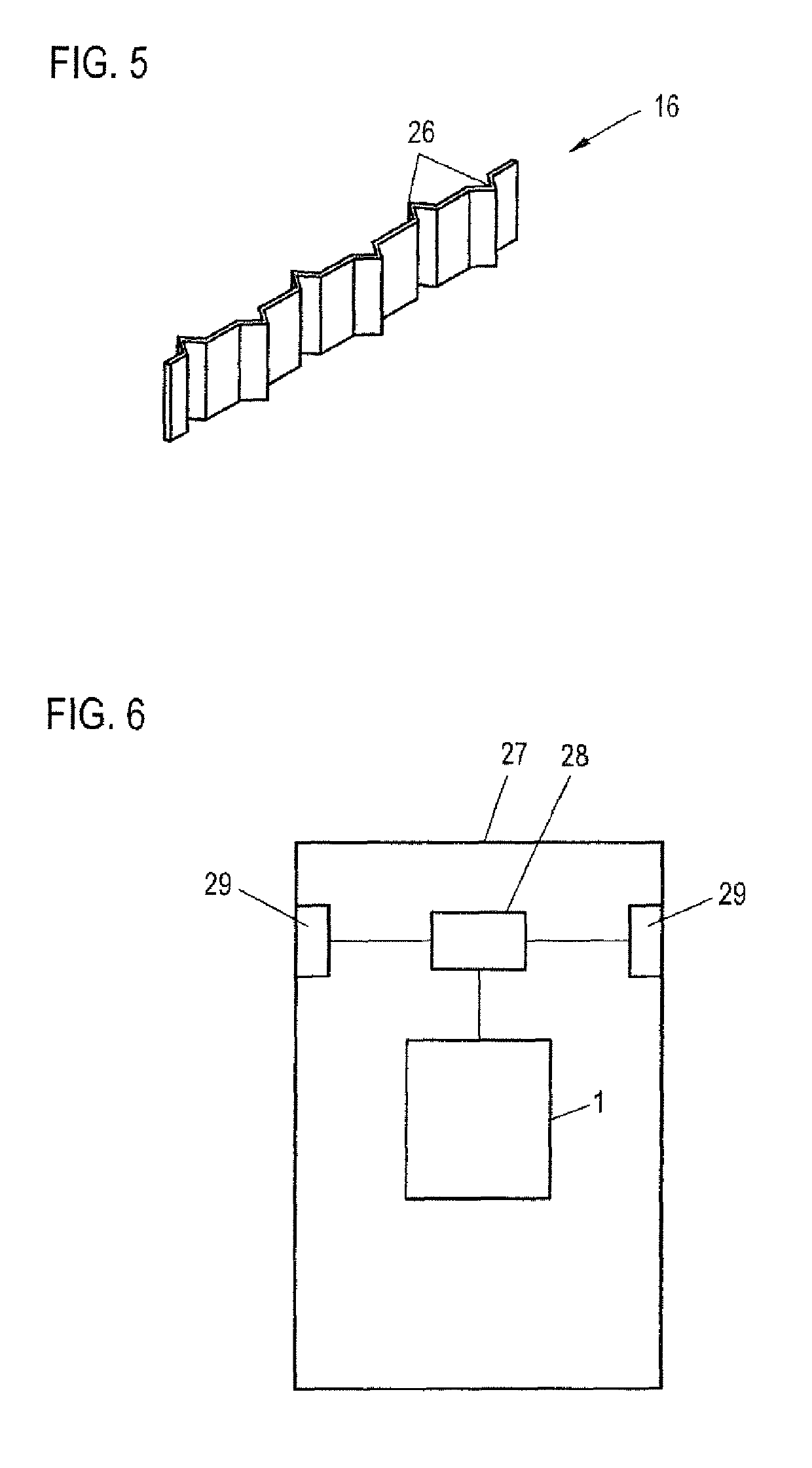
[0014]According to another advantageous feature of the present invention, a bulkhead can extend in axial and radial directions and split at least one of the flow passageways. The minimum distances normally results in flow passageways that have a cross sectional areas which permit only slight flow rates. Through the presence of a bulkhead in each of the flow passageways, flow sub-passages are created that enable greater flow rates for the cooling fluid. Advantageously, the bulkhead can be structured to generate turbulence in the cooling fluid flowing through the at least one of the flow passageways. This further enhances hydrodynamic properties of the flow passageways. Based on the recognition that the flow of cooling fluid has settled hydrodynamically and thermally in the flow passageway after a certain flow path, depending on the axial length of the electric machine, the formation of a turbulence-causing structure of the bulkhead results in swirling within the flow passageway. As a result, the flow has a higher Nusselt number and thus causes a higher heat transfer coefficient. Examples of a turbulence-causing structure include notches or indentations in the bulkhead, or an undulated or zigzag configuration.
[0020]According to another advantageous feature of the present invention, the coil carrier or a respective coil carrier segment can be made of multiple parts including an outer wall and a base body which is open towards the outer wall for receiving the outer wall to close the base body, with the outer wall being fastened to the base body. This configuration enables a simple arrangement of the stator coils in the coil carrier. Securement can advantageously be realized by a joining process which is suited to the material of the coil carrier. The outer wall can hereby extend in axial and circumferential directions, i.e. the outer wall has recesses for through openings, when a coil carrier with through openings is involved. In this case, the base body can have a trough-shaped configuration. As an alternative, it is, of course, also conceivable to provide an outer end wall for securement to the base body. This may cause a more complicated arrangement of the coils in the coil carrier, however, joining of base body and end wall can be realized in a particularly simple manner by providing only a circumferential joining seam.
[0023]According to another advantageous feature of the present invention, a bulkhead can extend in axial and radial directions and split at least one of the flow passageways. To further improve hydrodynamic properties, the bulkhead can be structured to generate turbulence in the cooling fluid flowing through the at least one of the flow passageways.

Problems solved by technology

As a result, any of the efficient cooling fluids, which cannot be used in conventional electric machines, may now find application.

Method used


Image

  • Electric machine for a motor vehicle, coil carrier for an electric machine, and motor vehicle
  • Electric machine for a motor vehicle, coil carrier for an electric machine, and motor vehicle
  • Electric machine for a motor vehicle, coil carrier for an electric machine, and motor vehicle

Examples


Embodiment Construction

[0034]Throughout all the figures, same or corresponding elements may generally be indicated by same reference numerals. These depicted embodiments are to be understood as illustrative of the invention and not as limiting in any way. It should also be understood that the figures are not necessarily to scale and that the embodiments may be illustrated by graphic symbols, phantom lines, diagrammatic representations and fragmentary views. In certain instances, details which are not necessary for an understanding of the present invention or which render other details difficult to perceive may have been omitted.

[0035]Turning now to the drawing, and in particular to FIG. 1, there is shown a basic cross sectional illustration of an electric machine according to the present invention, generally designated by reference numeral 1. The electric machine 1 includes a stator 2 and a rotor 3 which is coupled to a shaft 5 rotating about a rotation axis 4.

[0036]The electric machine 1 includes a coil ...


PUM


Abstract

An electric machine for a motor vehicle includes a rotor, and a stator interacting with the rotor. The stator includes a laminated core, a coil carrier configured for a flow of a cooling fluid there through, and a coil assembly having a plurality of stator coils and arranged in the coil carrier. The coil carrier has an enclosed configuration so as to form a fluid seal against the laminated core and the rotor.

Description

CROSS-REFERENCES TO RELATED APPLICATIONS[0001]This application claims the priority of German Patent Application, Serial No. 10 2016 001 838.0, filed Feb. 17, 2016, pursuant to 35 U.S.C. 119(a)-(d), the disclosure of which is incorporated herein by reference in its entirety as if fully set forth herein.BACKGROUND OF THE INVENTION[0002]The present invention relates to the field of electric machines for use in a motor vehicle.[0003]The following discussion of related art is provided to assist the reader in understanding the advantages of the invention, and is not to be construed as an admission that this related art is prior art to this invention.[0004]An electric machine for use in a motor vehicle should be able to provide a highest possible torque or power density. This, however, is accompanied by a high current density within the stator coils that is a major cause for overall losses of the electric machine. As a result, aspects of thermal stress resistance of such electric machines ...

Claims


Application Information

Patent Timeline
Patent Type & Authority Patents(United States)
IPC IPC(8): H02K9/19B60L1/02H02K3/24H02K1/14H02K3/28B60L50/50H02K3/52H02K9/197H02K1/16H02K1/20
CPCH02K1/20B60L1/02B60L50/50H02K1/14H02K9/197H02K3/24H02K3/28H02K3/522H02K1/16H02K3/46H02K9/19Y02T10/70
Inventor JURIS, PETER
Owner AUDI AG
Why Eureka
Try Eureka