
User equipment and radio base station

a radio base station and user equipment technology, applied in power management, orthogonal multiplex, multiplex communication, etc., can solve the problems of inability to allocate a certain radio resource, influence on the signal received by each user equipment, etc., to improve the overall system efficiency, improve the predictive index, and reduce the transmission power

Active Publication Date: 2019-07-16
NTT DOCOMO INC
View PDF11 Cites 0 Cited by
  • Summary
  • Abstract
  • Description
  • Claims
  • Application Information

AI Technical Summary

Benefits of technology

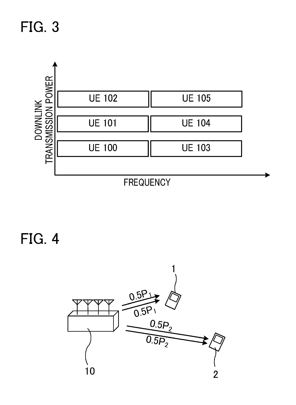
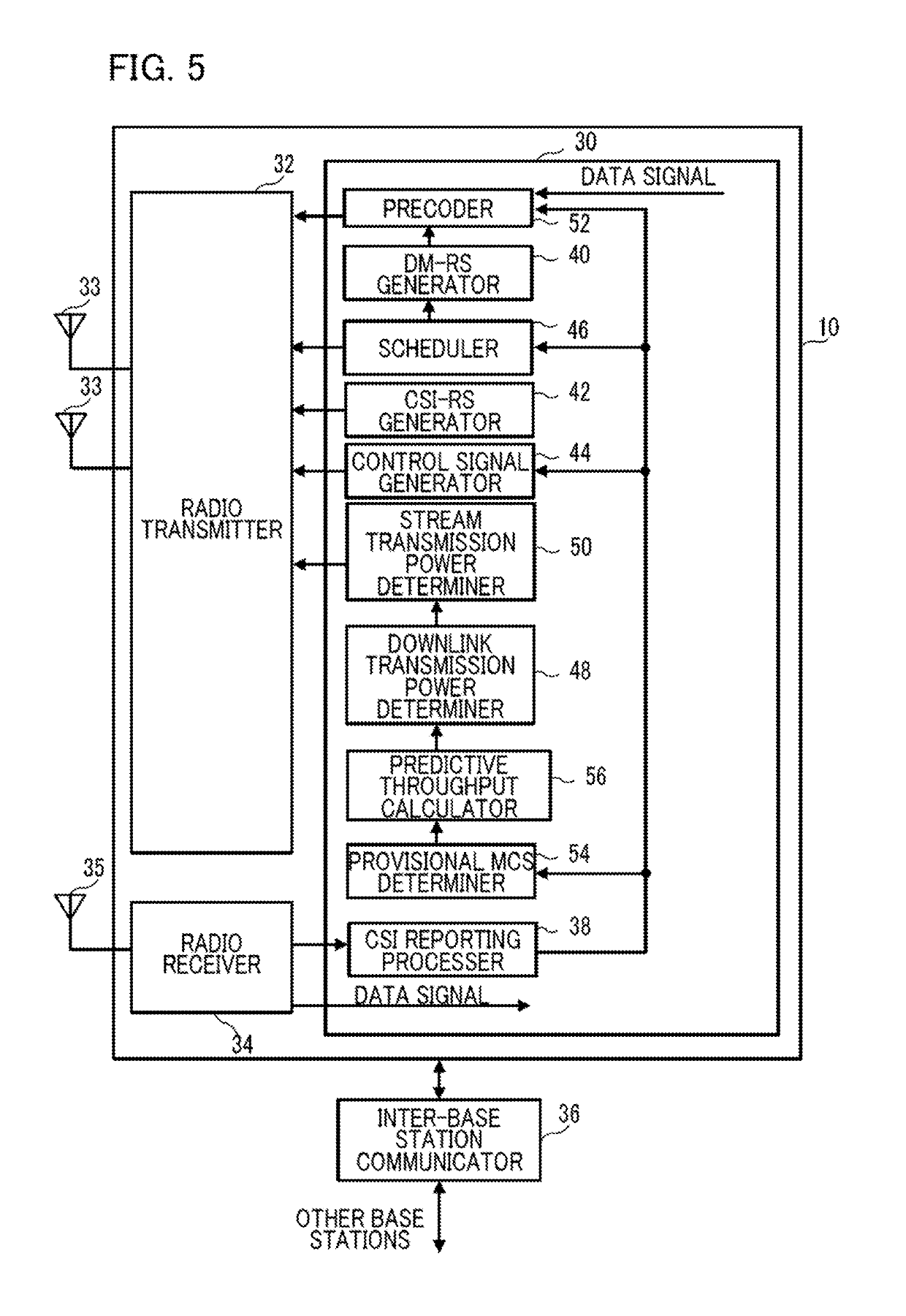
The present invention relates to a base station and a user equipment for non-orthogonal multiple access. The base station estimates predictive indices for user equipments based on channel state information determined by the user equipments. The base station allocates different transmission powers to the user equipments based on the predictive indices. The user equipment demodulates and decodes interference data signals regardless of the transmission power allocation. The desired data signal is appropriately decoded independent of the result of transmission power allocation. The user equipment does not need to know the necessity of canceling out interference data signals addressed to another user equipment from a received signal. This reduces the quantity of information notified from the base station to the user equipments and enables the user equipment to determine by itself whether to remove the interference data signal.

Problems solved by technology

Accordingly, the signal received by each user equipment is influenced by interference caused by signals addressed to other user equipments.
That is, in the case of using orthogonal multiple access alone, it is not possible to allocate a certain radio resource (e.g., a frequency) to multiple user equipments at the same time.

Method used


Image

  • User equipment and radio base station
  • User equipment and radio base station
  • User equipment and radio base station

Examples


Embodiment Construction

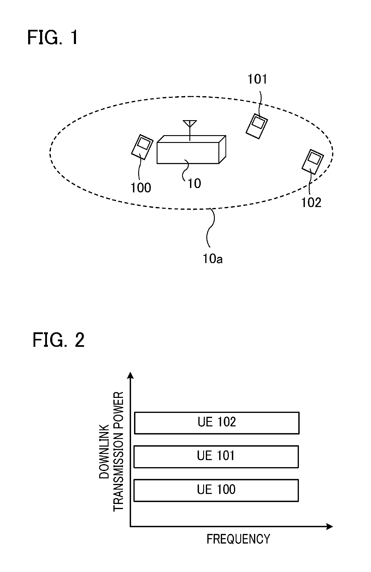
[0027]Hereinafter, various embodiments of the present invention will be described with reference to the accompanying drawings. First, an overview of non-orthogonal multiple access (NOMA) in the case of conventional SISO and / or SIMO will be described. As shown in FIG. 1, a base station 10 communicates with multiple user equipments (UEs) 100 to 102. In FIG. 1, reference numeral 10a indicates a cell area of the base station 10. The UE 102 is at the cell area edge, i.e., the position closest to the boundary of the cell area 10a, is the farthest from the base station 10, and has the largest path loss (i.e., has the smallest reception SINR). The UE 100 is near the center of the cell area 10a, is the closest to the base station 10, and has the smallest path loss (i.e., has the largest reception SINR). The UE 101 is closer to the base station 10 than the UE 102 is, and is farther from the base station 10 than the UE 100 is.

[0028]FIG. 2 is a diagram showing an example of allocation of downli...


PUM


Abstract

For each UE, a base station determines the number of streams for transmitting a data signal, performs different precoding on the data signal depending on the UE, and allocates different transmission powers to at least two UEs. The base station transmits streams addressed to the at least two UEs in a form in which these streams are non-orthogonally mixed, with transmission powers that are different for the UEs. For each of the streams addressed to these UEs, the base station estimates predictive indices for these UEs from channel state information determined by the UEs to which those streams are addressed, and, based on the predictive indices, allocates different transmission powers to those UEs such that the better the predictive index is, the lower the transmission power is.

Description

TECHNICAL FIELD[0001]The present invention relates to a base station, a user equipment, and a radio communication system.BACKGROUND ART[0002]Orthogonal multiple access (OMA), in which multiple signals do not interfere with each other, is widely used in communication between a base station and user equipments (e.g., mobile stations) in a mobile communication network. With orthogonal multiple access, different radio resources are allocated to different user equipments. CDMA (code division multiple access), TDMA (time division multiple access), and OFDMA (orthogonal frequency division multiple access) are examples of orthogonal multiple access. For example, in Long Term Evolution (LTE) standardized by the 3GPP, OFDMA is used in downlink communication. With OFDMA, different frequencies are allocated to different user equipments.[0003]In recent years, non-orthogonal multiple access (NOMA) has been proposed as a method for communication between a base station and user equipments (e.g., se...

Claims


Application Information

Patent Timeline
Patent Type & Authority Patents(United States)
IPC IPC(8): H04B1/16H04W52/26H04B7/06H04W52/24H04W72/04H04L5/00H04L1/00H04W52/14H04J11/00H04W88/02H04W88/08H04B7/0417H04L27/26H04W72/54
CPCH04W52/24H04J11/0043H04L1/0003H04L5/0048H04L5/0057H04W52/143H04W52/243H04W52/26H04W72/0473H04B7/0639H04W88/08H04B7/0417H04L5/0051H04L27/261H04W52/241H04W52/262H04W88/02H04L25/0224H04L25/03343
Inventor BENJEBBOUR, ANASSKISHIYAMA, YOSHIHISA
Owner NTT DOCOMO INC
Learn More